Instruction Manual
for
AS380 Series Elevator Integrated Drive Controller
72
5.1.3 Operator handling
5.1.3.1 Menu structure
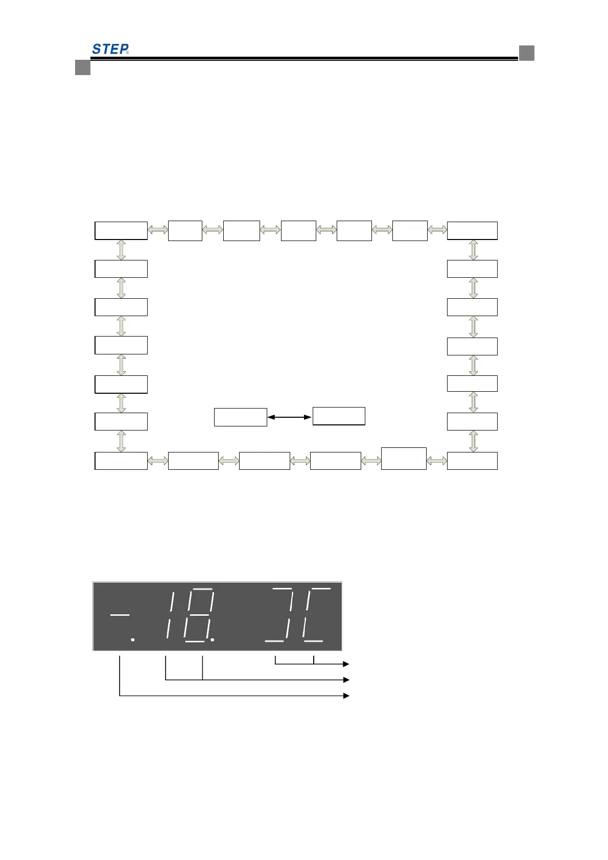
Main menu structure is as the below fig 5.2. the operation interface adopt the one level
menu structure due to the structure confinement of 7-segment and button. Press left and right
button to switch between various menu, press menu key to switch between LED function selection
and open/close door control.
Instruction
registered
Self-study
instruction
Front/rear
door allowed
Fault code
System year
System date
System time
Hoist way
parameter
Car top panel
input condition
Password
login
Process
diagnosis
Level -1 main menu
use”<””>”key to switch between
various menus
F value
setting
Control
parameter
reset
LED function
selection
Door open/close
control
MENU
key
Rear door
open allowed
Drive
parameter
reset
Floor display
Input type
Parking floor
allowed
Elevator speed
Elevator running
condition
Fault code
reset
Drive
program
version
Control
program
version
Fig 5.2 menu structure
5.1.3.2 Operation introduction for menus that use left or right button to switch
Press left or right button to switch between menus under the level-1 main menu interface.
The first interface displayed when power turn on is the elevator running condition interface. The
detailed introduction about the menu is as follow:
1 elevator running condition ( the menu display when power on)
Door condition
Floor
Running condition
This menu will display the basic condition of elevator, including running condition, floor
located, and door condition.
At the item: the running condition
 Loading...