Instruction Manual
for
AS380 Series Elevator Integrated Drive Controller
14
◎ Only trained, qualified and authorized
person may be allowed to work on elevator
integrated drive controller
Or it may cause risk of electric shock or
property damage.
◎ Always remove watches, rings or other metal
articles prior to working and always wear
suitable clothes and use appropriate tools
when working on elevator integrated drive
controller
Or it may cause risk of electric shock and
ex
losion.
1.6 operation notice
Please notice the following points when using AS380 series integrated drive controller.
1.6.1 Brake resistor selection
Elevator feature potential energy load, four quadrants movements’ characteristic,
and the occurrence of power-generation by braking. Therefore, users should consider adding brake
component to the integrated drive controller. Otherwise, tripping may be caused with overvoltage
fault. AS380 series integrated drive controller is equipped with brake unit, so only external brake
resistor is required. The specification table 1.1 for external brake resistor of integrated drive
controller
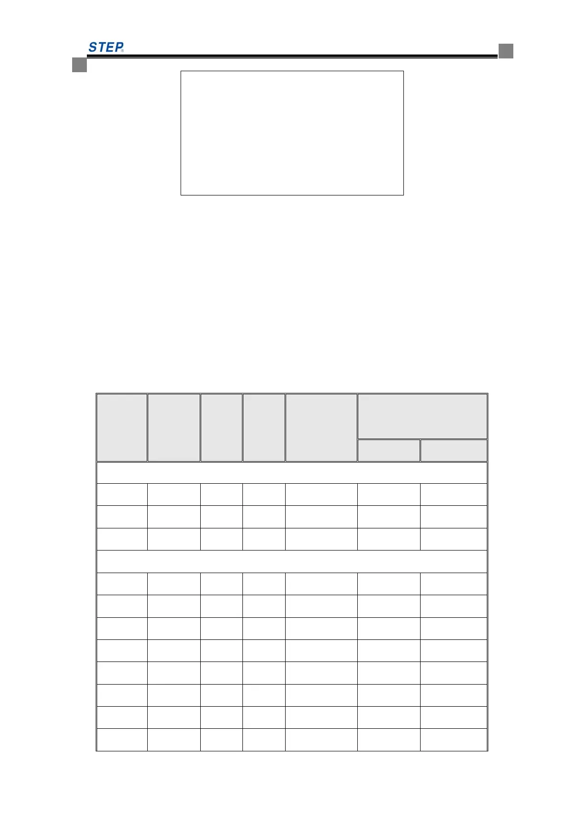
Table 1.1 AS380 series elevator integrated drive controller brake resistor configuration table
Model
No
AS380-
Matching
Motor
(kW)
Min
value
(Ω)
Max
value
(Ω)
Recommended
value
(Ω)
Recommended total resistor
capacity (W)
synchronous asynchronous
200V integrated device
2S01P1 1.1 26 72 64 1000 1000
2S02P5 2.2 26 58 50 1000 1000
2S03P7 3.7 26 39 30 1600 1200
400V integrated device
4T02P2 2.2 56 210 100 1000 1000
4T03P7 3.7 56 144 80 1600 1200
4T05P5 5.5 56 100 70 2000 1600
4T07P5 7.5 56 72 64 3200 2000
4T0011 11 34 48 40 4000 3200
4T0015 15 34 41 36 5000 4000
4T18P5 18.5 17 31 24 6400 5000
4T0022 22 17 27 20 8000 6400
 Loading...