Instruction Manual
for
AS380 Series Elevator Integrated Drive Controller
116
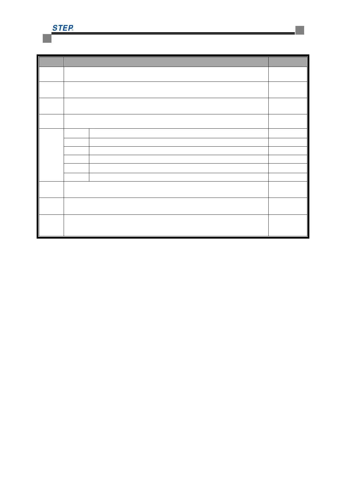
☆ Terminal Definition and Plug-in Specification on SM-04-VHL
Serial Descriptions Remarks
JP5
Serial port, of which Pin 1 for TXV+, Pin 2 for TXV-, Pin 3 for TXA+ and Pin 4
for TXA- respectively.
CH3.96-4
JP4
Down-call terminals, of which Pin 3+ and Pin 4- for button indicator, Pin 1 and
Pin 2 for button input.
CH2510-4
JP6
Up-call terminals, of which Pin 3+ and Pin 4- for button indicator, Pin 1 and Pin
2 for button input.
CH2510-4
JP8
Pin 1 and Pin 2 JP8 for the input of normal open contact of the lockout switch,
Pin 3 and Pin 4 for stand-by.
CH2510-5
JP2
JP2.1 output terminal for landing arrival gong up CH2510-4
JP2.2 common port for landing arrival gongs up and down
JP2.3 output terminal for landing arrival gong down
JP2.4 output terminal for landing arrival lamp up
JP2.5 common port output for landing arrival lamp up and down
JP2.6 output terminal for landing arrival lamp down
JP7
Resistor jumper for serial communication terminals for connecting the 120Ω
built-in resistor when jumpers are put on together.
S1
Set the address codes of the display Board with the jumper on, after that the
jumper MUST BE REMOVED.
S2
Inserting the jumper on the landing call display Board of the elevator locked out
shows the lockout input on this Board in effect. Only ONE of the display Boards
of the elevator shall be jumped to S2.
List 6.13 Terminal Definitions and Specification of SM-04-VHL
6.5.4 Call & LCD Control Board SM-04-UL
☆ 6.21 Outside View & Mounting Dimensions of SM-04-UL
 Loading...