Instruction Manual
for
AS380 Series Elevator Integrated Drive Controller
232
See attached Table A1.1 for basic noise suppression measures.
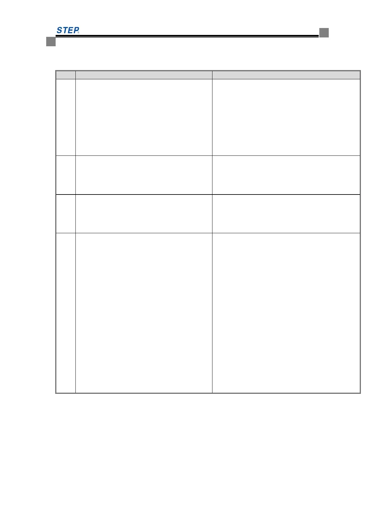
Attached Table A1.1 Basic Noise Suppression Measures.
No. Causes Measures
①
⑦
⑧
Due to electromagnetic induction and
electrostatic induction where signal lines are
arranged in duplex with power lines or arranged
in bundle, noises occurs and transmits in signal
line and additionally results in malfunction of
peripherals
1. Avoid arranging signal line and power line in
duplex and in bundle.
2. keep susceptible peripherals far away from
elevator integrated drive controller;
3. keep susceptible signal line far away from the
input/output cable of elevator integrated drive
controller;
4. Use shielded lines as signal line and power line.
It is better to put them in metal hoses (hose-to-hose
spacing shall not be less than 20cm )
②
Where closed loop circuit is formed among
peripherals and elevator integrated drive
controller, the grounding leakage current of
integrated drive controller may cause malfunction
of peripherals.
If that time the peripherals are not grounded, the
malfunction due to leakage current may be avoided.
③
When peripherals sharing a power supply system
with elevator integrated drive controller, the
noise of elevator integrated drive controller may
transit along the supply line and resultantly cause
malfunction of the related peripherals.
Connect a noise filter at the input side of elevator
integrated drive controller; or isolate the peripheral
from noise by isolating transformer/supply filter.
④
⑤
⑥
When such weak voltage equipment as control
computers, measuring gauges, radio sets and
sensor and their signal lines are installed in a
same control cabinet with elevator integrated
drive controller and are wired very close to each
other, the radiated interference may cause
malfunction of peripheral.
1. Susceptible peripherals and their signal lines must
e arranged far away from elevator integrated drive
controller. Furthermore, the signal line shall be of type
shielded line which shielding layer is properly
grounded. Signal line shall be threaded into metal hose
and arranged far away from the input/output cable of
elevator integrated drive controller. These two kinds of
cable shall be perpendicular to each other.
2. radio noise filter and linear noise filter (ferrite
common mode choke) as installed at both input side
and output side of elevator integrated drive controller
will be effective for suppress its noise radiation;
3. the cables of elevator integrated drive controller
shall be arranged in thicker shielding layer such as
ducts with thickness 2mm or be embedded in cement
tray. In addition, the cables must be threaded in
grounded metal hose. (Four-core cable may be
appreciable for motor cable. One end of a core
conductor shall be grounded to the elevator integrated
drive controller side and another end shall be
connected to motor casing.
A2 Requirements on Cable Laying
A2.1 Requirement on Cable Laying
As shown by figure A2.1(a): To prevent mutual coupling of interferences, control signal cable
must be laid separately with supply cable and motor cable and be spaced as far as practicable. as
shown by figure A2.1(b): where the control signal cable has to cross over supply cable or motor
cable, they must be perpendicular with each.
 Loading...