Instruction Manual
for
AS380 Series Elevator Integrated Drive Controller
188
(4) By Inspection operation on the car top, confirm that the motion and movement position of the
deceleration switch at the end of the well terminal are correct.
(5) By Inspection operation on the car top, confirm that the well leveling switch and leveling
spiles are installed correctly; at all leveling positions, each leveling switch motions at the right
point.
8.5.3 Check of CAN Communication Lines and Setting of 04 Board Address
1. Check of communication terminal resistance:
(1) Confirm that the terminal resistance between the CAN 1 communication port TXA + and
TXA- is 60 ohms (inside the car and outside the hall there is a respective jumper terminal
resistance of 120 ohms).
(2) Confirm that the terminal resistance of CAN2 communication port TXA1 +, TXA1-parallel
connection or group control is 60 ohms (for parallel connection or group control elevator, the
terminal resistance at motherboard CAN2 port should be inter-connected.)
2. Setting of SM-04 board address
Please start from the lowest order, set the SM-04 board address from 1 until the top end. Set the
SM-04 address inside the car to 0. Note that: if it is parallel connection or group control, the
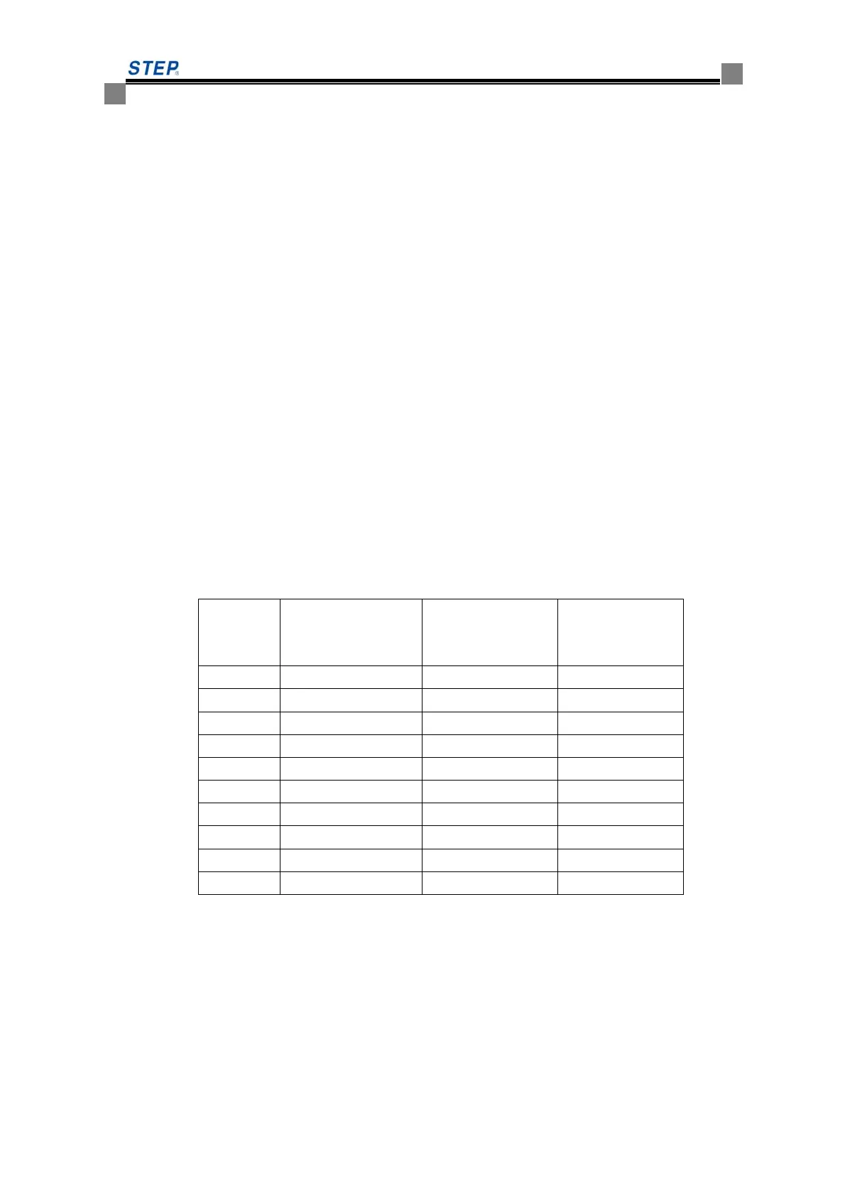
address sequence is based on the order of the entire elevator group. For example: three elevators A,
B, C for group control, Elevator A serves floor -2, -1,1,2 ~ 8; B serves -1,1,3 ~ 8; C serves 1,2,4 ~
7. Then set the SM-04 board of each elevator to the address as shown below.
Floor Elevator A
Board SM-04
Set Address
Elevator B
Board SM-04
Set Address
Elevator C
Board SM-04
Set Address
-2 1 × ×
-1 2 2 ×
1 3 3 3
2 4 × 4
3 5 5 ×
4 6 6 6
5 7 7 7
6 8 8 8
7 9 9 9
8 10 10 ×
The "×" in the table above indicates that there is no SM-04 board on the floor. In specific
settings, first set the address switch on the SM-04 board (SW5.1 or SW1.4) to ON position, or set
the address to the jumper pin (S1) or short with a short circuit cap (whether it is switch or jumper
pin and what the switch code should be is determined by different types of SM-04 board. Refer to
Section 6.3 Definition of Display Penal Port). Then, power on the SM-04 board, it is in the
address setting state, the normal display of the elevator location now shows the address of SM-04
board. Press the up and down buttons to adjust the address data upward and downward, until the
address displayed shows that the SM-04 board should set on this floor. Finally, reset the address
setting switch or the jumper pin to make SM-04 board back to normal operation.
 Loading...