Instruction Manual
for
AS380 Series Elevator Integrated Drive Controller
69
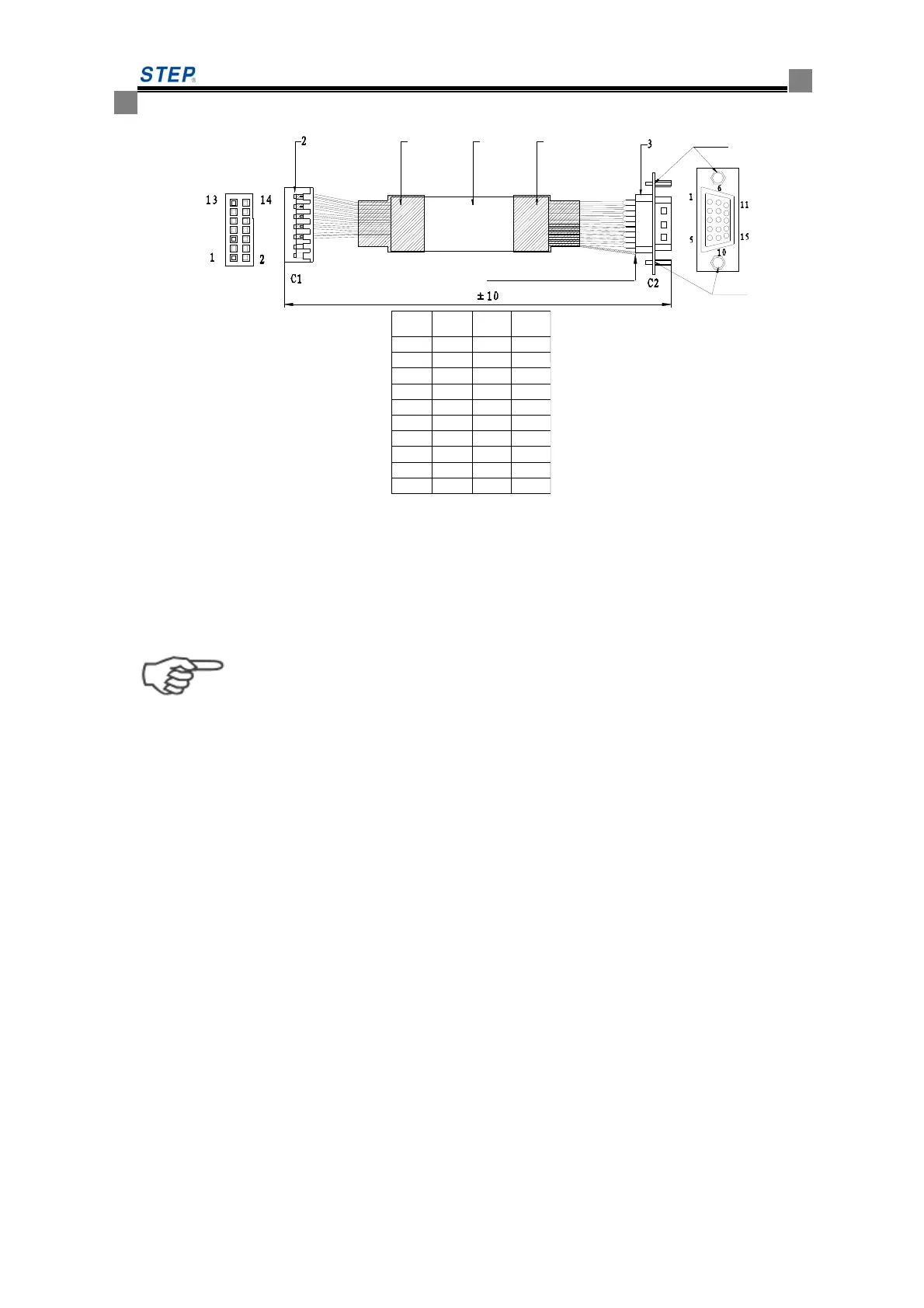
M3螺母
M3螺母
屏蔽层焊于DB插头的铁壳上
310
1 44
C1
塑壳2*7
C2
DB15母头
信号
PIN 5
PIN 6
PIN 7
PIN 8
PIN 14
PIN 13
PIN 9
PIN 10
PIN 11
PIN 12 PIN 11
PIN 12
PIN 5
PIN 6
PIN 14
PIN 13
PIN 1
PIN 2
PIN 3
PIN 4 cos-
对应颜色
cos+
sin-
v+
GND
dat-
dat+
clk-
clk+
sin+
红
黄
橙
红/白
黄/黑
橙/黑
蓝/黑
蓝
绿
绿/黑
Fig 4.25 Endat absolute value tieline definition
4.7.5 Notice item for PG card terminal wiring
Important
Encoder signal line should be arranged separately with main circuit and other power line. Do not
arrange the lines in close parallel. The encoder wiring is shield line. Shield layer of shield line
should be connected to terminal grounding PE
 Loading...