Instruction Manual
for
AS380 Series Elevator Integrated Drive Controller
57
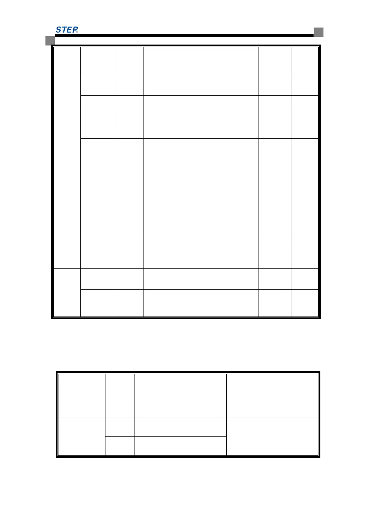
JP9.8 X17 door interlock circuit relay inspection Input
Normal
close
JP9.9 X18
upward No 2 terminal deceleration
switch
Input
JP9.10 X19
downward No 2 terminal deceleration
Input
JP10
JP10.1 +24VIO
input isolating power supply +24v,
internally connect to JP7.5
JP10.2 VSIO
Externally connect to JP 10.1, Effective
low level input, at this time JP10.3 as
input common port. Externally connect to
JP10.3, effective high level input, at this
time JP10.1 as input common port.
JP10.3 G24VIO
input shield power OV, internally connect
with JP7.4
JP11
JP11.1
0V analog quantity input 0V
JP11.2
AIN- differential analog quantity input-
JP11.3
AIN+ differential analog quantity input+
Note:The connection on the load cell is as follows:the sensor simulation quantity output is
connected to JP11.3. the sensor 0V connect to JP11.2 and JP11.1 and JP11.2 should be shorted.
4.6.3 Dip switch setting method
SW2
ON
Monitoring CAN terminal
resistor effective condition
SW2 default setting is OFF;
OFF
Monitoring CAN terminal
resistor invalid condition
SW3
ON program recording condition
Default setting is OFF
(keep OFF condition when in
use)
OFF normal working condition
 Loading...