Instruction Manual
for
AS380 Series Elevator Integrated Drive Controller
238
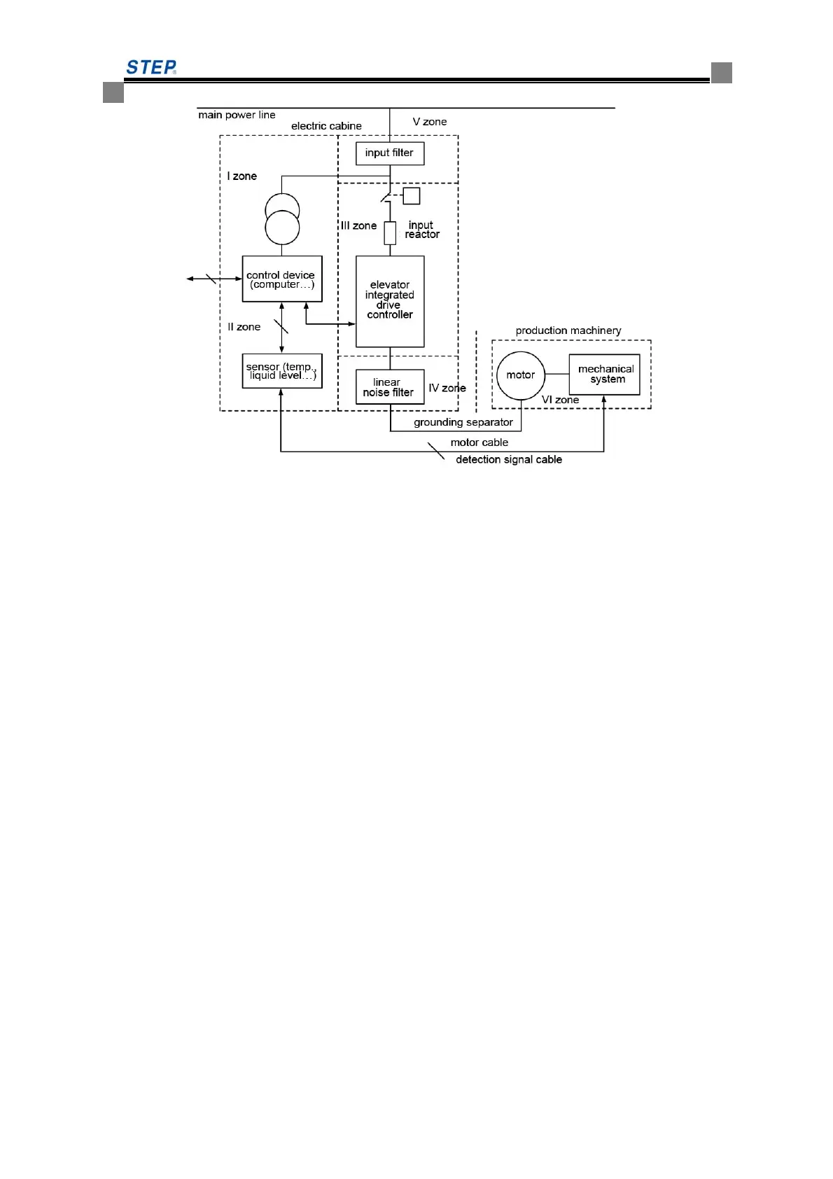
Figure A8.1 EMC Zone for installation of elevator integrated drive controller
Description of above shown EMC zoning for installation:
I zone: Control supply transformer, control device and sensor
II zone: Control signal cable interface requiring certain anti-interference capacity
III zone: Main noise sources including input reactor, elevator integrated drive controller, brake
unit, contactor and the like
IV zone: Output noise filter and its wiring
V zone: Power supply (includes wiring of radio noise filter)
VI zone: Motor and its cable
These zones shall be separated by minimum 20cm in order to realize electromagnetic decoupling;
for better decoupling effect, ground separator is preferred among the zones. The cables shall be
laid and arranged by zone; if necessary, filters shall be installed at interfacing point between zones;
all the bus cables led out from cabinet (e.g. RS485) and signal cable must be shielded.
A9 Precautions for Electric Installation
See Figure A9.1 for electric installation of elevator integrated drive controller.
 Loading...