Home
STEP
Controller
AS380-4T07P5
STEP AS380-4T07P5 User Manual
5
of 1
of 1 rating
271 pages
Give review
Manual
Specs
To Next Page
To Next Page
To Previous Page
To Previous Page
Loading...
Instruction Manual
for
AS380 Series Elevator Integrated Drive Controller
1
17
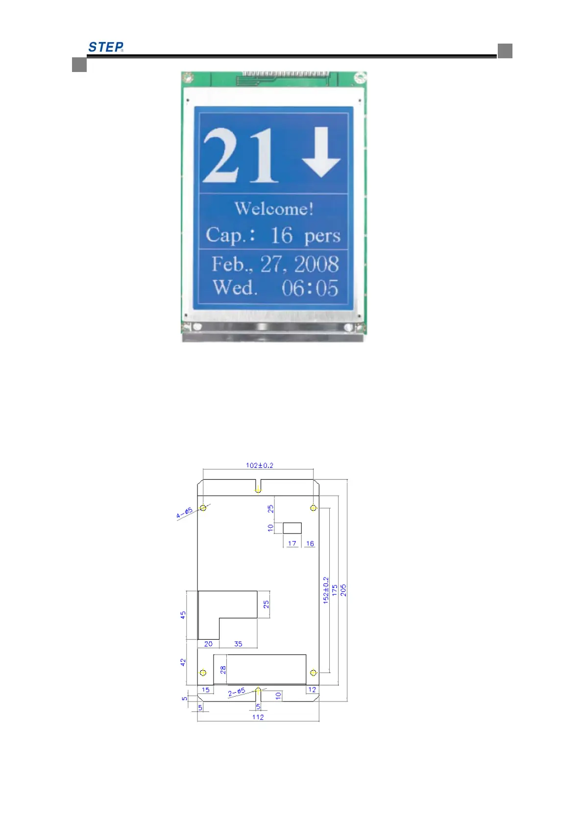
Dimension sp
ecification
:
O
utside Dimension: 16
0 x 109 cm,
LCD display dim
ension: 1
10 x 86 cm
W
orking temperature
:
-10 degree---60 degree
W
orking humidity
:
<
95%
55
out
side view and installa
tion size
Fig. 6.22 outside
V
iew of
SM-04-UL
116
118
Table of Contents
Default Chapter
6
Table of Contents
6
Chapter One: General Knowledge of the Integrated Drive Controller
11
Scope of Application
11
Items in the Cases
11
Model Description
11
Integrated Drive Controller Nameplate
12
Notice Items for Safety
12
Operation Notice
14
Absorber at the Output Side Prohibited
15
The Application Voltage of Integrated Device
15
Two-Phase Input Not Allowed
15
Altitude and Derated Application
15
Synchronous Sealing Star Delay
16
Waste Disposal
16
Disposal of Capacitors
16
Disposal of Plastic Components
17
Chapter Two: Model and Specification
18
Model of Integrated Drive Controller
18
The Technical Specification of Integrated Drive Controller
18
The Installation Dimensions and Mass of the Integrated Drive Controller
24
Installation Instructions
25
Product Installation Location
26
Product Installation Positioning and Clearance Requirements
26
Chapter Three: Product Function
28
Function List
28
Elevator Operation Function Description and Setting Method
30
Standard Function Description
30
Optional Function Description
35
Chapter Four: Wiring of Elevator Integrated Drive Controller
38
The Connection between Integrated Drive Controller and Peripheral Equipments
39
For Typical Terminal Wiring Diagram of Elevator Integrated Drive Controller
39
Notice Items for Peripheral Equipments Connection
39
Power Supply
39
Breaker
40
AC Reactor at the Input Side
40
Interference Filter at the Input Side
40
Main Circuit Output Contactor
40
Interference Filters at the Output Side
40
AC Reactor at Output Side
40
DC Reactor
40
The Technical Requirements for Wire Arrangement of Peripheral Equipments of the Elevator Integrated Drive Controller
41
The Cable Requirement of Hoist Way and Accompanying Cable Arrangement
41
Method of Wiring between Call Board and TXV+、TXV-、TXA+、TXA
42
3Hoist Way Switch Position
43
Upper and Lower Leveling Inductor
44
Main Circuit Terminal Wiring
45
The Arrangement of Main Circuit Terminal
45
The Main Circuit Terminal Labeling and Function Description
45
Main Circuit Wire Specification
46
The Main Circuit Composition
48
The Detailed Description of Main Circuit Terminal Wiring
48
Anti-Interference Measures
52
The Specialized Noise Filter Connected at the Output Side
52
Main Circuit Wiring Arrangement
52
The Better Anti-Interference Measure
53
Relation between Wiring Length and Carrier Frequency
53
Wiring of Control Circuit Terminals
54
Layout of Control Circuit Terminals
54
Functional Description of Control Circuit Terminals
54
B.2 Fault Code and Analysis
55
Dip Switch Setting Method
57
Wire Specification of Control Circuit
58
Notice Items for Control Circuit Terminal Wiring
60
The Wires of PG Card Terminal
60
ABZ Incremental 12V PG Card
60
ABZ Incremental 5V PG Card
65
Endat Absolute Value PG Card
67
Notice Item for PG Card Terminal Wiring
69
Chapter Five :Operator
70
LED Indicator Light
70
Function Key
70
Operator Handling
72
Graphic Symbol of Number and Letter on LED Screen
86
LCD Handheld Operator
87
LCD Handheld Operator Introduction
87
Handheld Operator Connection Method
88
Handheld Operator Function
89
Introduction to Display Interface of LCD Hand-Held Operator
90
Chapter 6 Introduction to the Supporting Products
100
Car Top Control Board SM.02/H Introduction
101
Car Top Control Panel SM.02/H Outside View and Installation Dimension
101
Car Top Control Panel SM 02/H
102
Car Top Extension Board SM09I0/B Introduction
104
Car Top Extension Board SM09IO/B Outside View and Installation Dimension
104
Car Top Extension Board SM09IO/B Plug-In and Port Definition Introduction
105
Car Controller Panel SM.02/G Introduction
106
Car Controller Panel SM02/G Outside View and Installation Dimension
106
Car Control Board SM.02/G Plug-In and Port Definition Introduction
107
Instruction Control Board SM-03
109
Instruction Control Board SM-03 Outside View and Installation Dimension
110
Instruction Controller Board SM-03 Plug-In and Port Definition Introduction
110
Call & Display Control Board
111
Call &Display Control Board SM-04-VRFS
111
Call& Display Control Board SM-04-HSC
113
Call & Display Control Board SM-04-VHL
115
Call & LCD Control Board SM-04-UL
116
Car Call & LCD Control Board SM-04-VL
118
In-Car SM-04-VL/B3 Outside View and Installation Dimension
121
Call& LED Display Control Panel SM-04-VSD
123
Call & LED Display SM-04-VRJ
124
Miscellaneous (a List of Display Codes)
125
SM-GC Board Introduction
128
System Structure
128
2Basic Feature
128
3Main Functions
129
Overall Adjustment Principle
131
Treatment in Special Situation
132
Detailed Description of Group Controller
132
Connection Diagram of Group Control System
136
Chapter 7 Parameter Table of Integrated Drive Controller
143
F Parameter List
143
Definition of Function Parameter
157
Check before Power
182
Power on and Check
182
Confirmation before Power on
182
Checks after Power on
183
Configuration of System Basic Parameters and Self Study of Motor Parameters
184
Configuration of System Basic Parameters
184
Motor Parameter Self Study
185
Test Run of Slow Car
186
Inspection Operation of Engine Room and Preparations for Express Car
186
Car Top Inspection Operation
187
Check of CAN Communication Lines and Setting of 04 Board Address
188
Door Opening/Closing Adjustment
189
Hoist Way Self Study
189
Hoist Way Self Study Method
189
Express Car Operation
190
Adjust Elevator Comfort
193
Factors Relating to Elevator Comfort in Operation
193
Adjust Elevator Comfort
194
Leveling Adjustment
202
Method for Adjusting Pre-Load Weighing Compensation at Elevator Start
208
Use of DTZZ-III-DC-SC
210
Use of Non-DTZZ-III-DC-SC Weighing Device (F164 Set to 1, 2, 5 or 6) to Compensate or
211
Adjust the Start
211
Simple Compensation by Using Light-Load and Heavy-Load Switch (F164 Set to 4)
211
The Adjustment of Other Function
212
Chapter 9: Faults and Solutions
213
The Fault Analysis of the Integrated Device Control System
213
Fault Analysis of Integrated Drive System
220
Chapter 10: Maintenance
228
Warranty
228
Product Checkup
228
Routine Inspection
229
Periodic Inspection
229
Appendix Aemc Installation Guide
231
A1 Noise Control
231
A1.1 Noise Type
231
A1.2 Transmission Path
231
A1.3 Basic Measures for Noise Suppression
231
A2 Requirements on Cable Laying
232
A2.1 Requirement on Cable Laying
232
A2.2 Requirements on Cable Size
233
A2.3 Requirements on Shielded Cable
233
A2.4 Requirements on Installation of Shielded Cable
233
A3 Grounding Requirements
233
A3.1 Grounding Method
233
A3.2 Precautions for Grounding Connection
234
A4 Install Surge Absorption Device
234
A5 Leakage Current and Countermeasures
235
A5.1 Ground Leakage Current
235
A5.2 Line-To-Line Leakage Current
235
A6 Suppression of Radiated Emission
236
A7 Guide for Use of Power Line Filter
236
A7.1 Functions of Power Line Filter
236
A7.2 Precautions for Installation of Power Line Filter
237
A8 EMC Installation Zoning
237
A9 Precautions for Electric Installation
238
A10 EMC Conformity
240
Appendix B Function Parameter, Fault List Summary
241
B.1 Function Parameter List
241
Notice to Customers
270
5
Based on 1 rating
Ask a question
Give review
Questions and Answers:
Need help?
Do you have a question about the STEP AS380-4T07P5 and is the answer not in the manual?
Ask a question
STEP AS380-4T07P5 Specifications
General
Brand
STEP
Model
AS380-4T07P5
Category
Controller
Language
English
Related product manuals
STEP AS380-4T05P5
271 pages
STEP AS380 Series
300 pages
 Loading...