Instruction Manual
for
AS380 Series Elevator Integrated Drive Controller
112
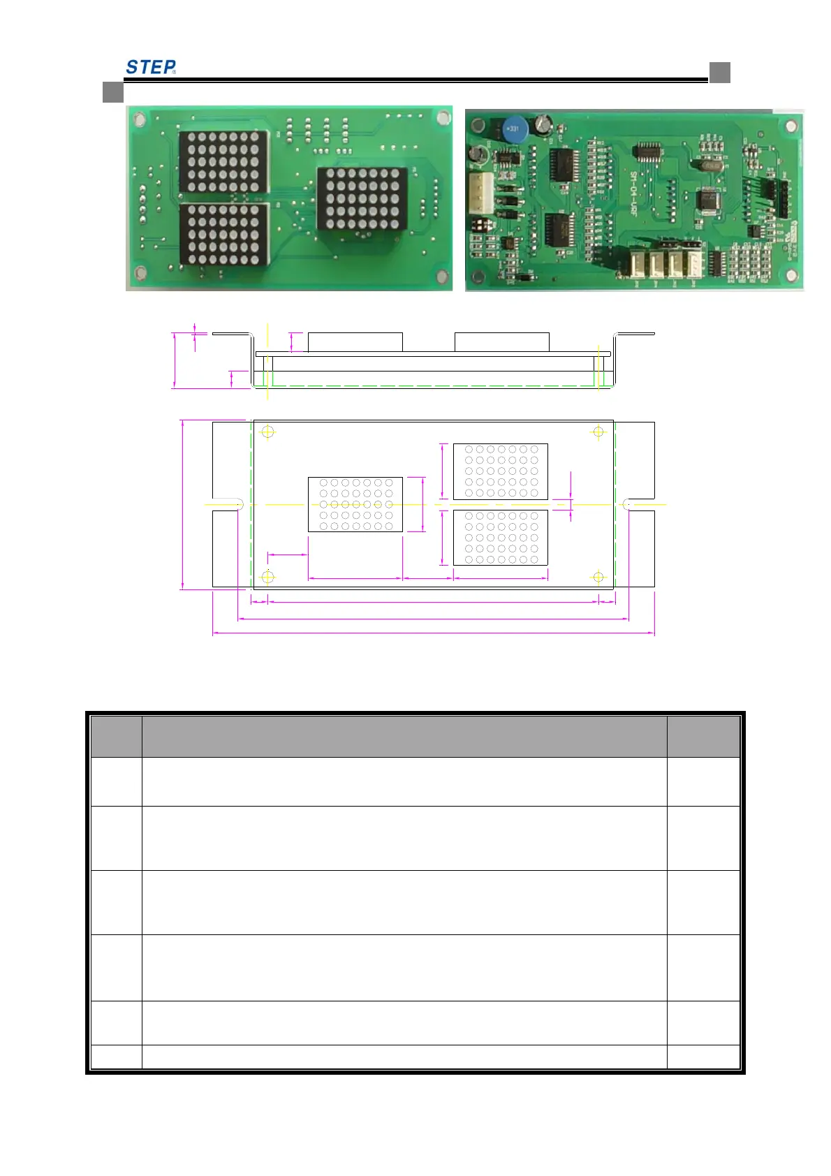
Fig 6.11 SM-04-VRF outside view
7
23
1
182.5
8
161.5
22.5
39
70
21 39
4.5
22.5
22.5
16.5
7 7136.5
Fig 6.12 SM-04-VRF installation dimension
☆SM-04-VRF plug-in specification and port definition
Table 6.9 SM-04-VRF plug-in specification and port definition
Serial
No
description
remark
JP1
Serial communication port,in which pin 1 as TXV+, pin 2 as TXV-,pin 3 as TXA+,
pin 4 as TXA-
CH3.96-4
JP2
upward call button port (pin 1,2 as button lamp indicator, 1 as “-“, 2 as “+”, pin 3 and
4 as button input
CH2510-
4
JP3
downward call button port (pin 1,2 as button lamp indicator, 1 as “-“, 2 as “+”, pin 3
and 4 as button input
CH2510-
4
JP4
stop indicator( hall)/overload output (car) and elevator lock input port (pin 1,2 as
button lamp indicator, 1 as “-“, 2 as “+”, pin 3 and 4 as normal open contact input of
elevator lock switch)
CH2510-
4
JP5
Full-load indicator( hall)/firefighting output (car) (pin 1,2 as button lamp indicator, 1
as “-“, 2 as “+”, pin 3 and 4 as standby input)
CH2510-
4
JP6
program burning slot/RS232 communication port
 Loading...