Instruction Manual
for
AS380 Series Elevator Integrated Drive Controller
197
stop. The greater I0 is, the shorter the response time is. If the I0 value is too small, P0 will not have enough time to
motion; if I0 is too large, high frequency oscillation may be easily produced. D0 helps the system with the
response speed. The larger D0 is, the faster response is; but too large D0 can cause oscillation.
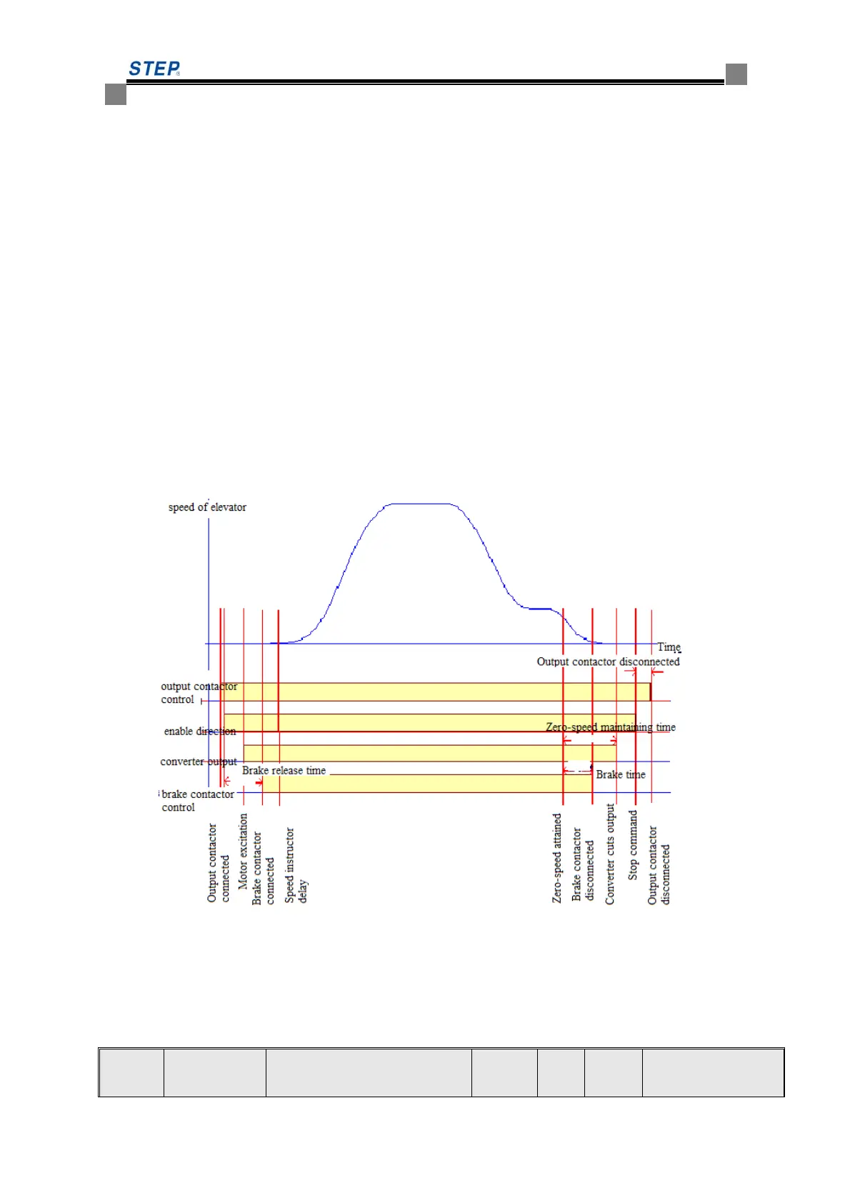
(b) Adjust timing sequence to improve starting comfort
The starting timing sequence is the coordination between the main contactor pull, the release
of inverter upward or downward command (or enable signal), brake open and the speed signal,
when the elevator starts. In general, at the elevator starter, the main contactor pulls first, then
inverter enable signal releases, and then the brake open and the speed reference command give out.
The order between the speed reference and the brake has a great impact on the starting comfort of
the elevator. The ideal coordination point is: at the mechanical movement (really open) of the
brake, the speed reference is given. However, due to the brake contactor delay and the mechanical
brake delay, it is not easy to give accurate data for the two motions to achieve the desired effect.
The following principles may be observed for adjusting timing sequence: in no-load operation, if
the downward start shows an obvious pull back, postpone the opening time of the brake (or set the
reference speed earlier; if the downward start shows a weak pull back, but an obvious push for the
upward start, set the brake o timing diagram at start and stop.
Diagram 8.2 Adjustable Timing Sequence Diagram
2) Comfort adjustment during operation
By adjusting the PID regulator parameters at each speed segment in the elevator running process,
the comfort can be improved. The adjusting parameters are as follows.
Function
Code
Name Content Scope Unit
Factory
Setup
Remarks
 Loading...