7-4
764333-098
when removing clamps and replacing squeeze
tube. Residual detergent might remain in used
squeeze tube. If detergent contacts skin or eyes,
immediately flush with running water for at least
10 minutes. If contact was with the eyes, seek
medical attention.
1. Lock building electrical supply disconnect switch
in OFF position and close unit supply valves.
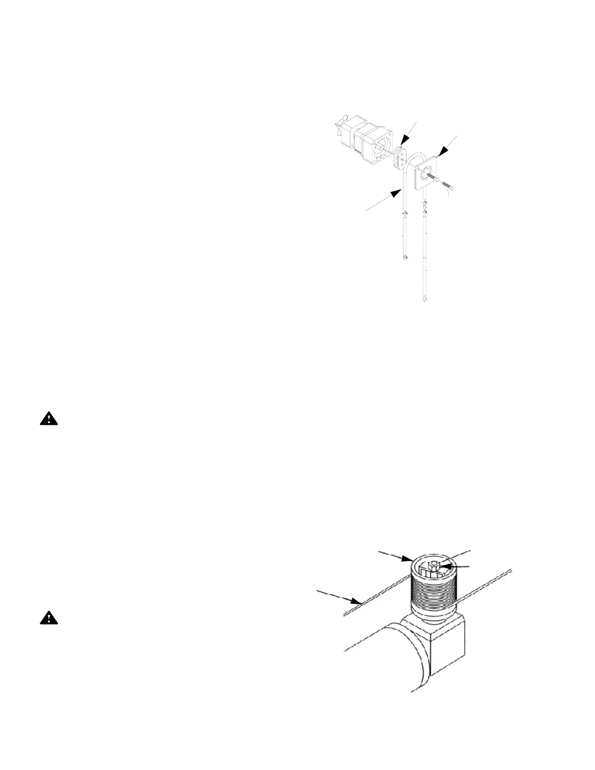
2. Remove two screws attaching pump cover to pump
head. Lift cover away from head.
3. Pulling on one end of squeeze tube, pull tube out of
pump head.
4. Using an Allen hex key, remove setscrew. Lift roller
block out of head.
5. Remove two screws holding head in place. Pull
head away from pump motor.
NOTE: Make note of electrical connections for reas-
sembly.
6. Unplug pump and remove two screws attaching
base of pump assembly to bracket. Remove pump
assembly from detergent compartment.
7. Untighten nut holding ground to motor.
8. Disconnect all electrical connections from the
motor.
9. Remove two screws fastening motor to pump
assembly base.
CAUTION – POSSIBLE EQUIPMENT DAM-
AGE: Ensure a cooling fan is attached to rear
motor shaft. Check that the fan blades are posi-
tioned to send airflow to motor. Motor will overheat
without a cooling fan.
10.Remove propeller and install on new motor.
11.Attach new motor to pump assembly with screws
previously removed.
12.Reconnect all electrical connections.
13.Tighten nut holding ground to motor.
14.Plug pump and secure with two screws previously
removed.
15.Reinstall head and secure with two screws previ-
ously removed.
CAUTION – POSSIBLE EQUIPMENT DAM-
AGE: Carefully tighten setscrew. Metal set-
screw can easily strip plastic threads in roller block
assembly.
16.Reinstall roller block and secure with set screw
previously removed.
17.Reinstall squeeze tube.
18.Reinstall pump cover to pump head kit with two
screws previously removed.
19.Initiate a cycle and check pump motor operation.
7.5 CARRIAGE DRIVE
7.5.1 Adjusting Carriage Drive Clutch
1. Set POWER-OFF/STANDBY switch to OFF/
STANDBY. Lock disconnect switch in OFF position
and close building supply valves.
2. Remove safety cover from top of drive motor cap-
stan.
3. Loosen setscrews on 3/4" adjusting nut located in
center of capstan (see Figure 7-4).
4. Tighten adjusting nut in 1/16 turn increments until
carriage moves smoothly back-and-forth.
5. Tighten setscrews and replace safety cover.
6. Re-energize washer utilities.
Figure 7-3. Replace Pump Motor
Roller Block
Pump Cover
Squeeze Tube
Figure 7-4. Drive Clutch
Capstan
Cable
Adjusting
Nut




 To Next Page