7-5
764333-098
7.5.2 Adjusting Carriage Drive Cable
Evenly tighten eye bolts, located in center of carriage
to remove slack from cable. Ensure adjusting eye bolts
evenly to maintain a centered carriage.
NOTE: There should be a minimum of one or two inches
(25 to 50 mm) free play in cable.
7.5.3 Replacing Carriage Drive Cable
• Remove old drive cable as follows:
1. Lock disconnect switch in OFF position and close
building supply valves.
2. Loosen eye bolts, located in center of carriage, until
only one full nut of threads remains on each.
3. Disconnect drive cable from carriage by removing
cable clamps and pulling ends of cable out of eye
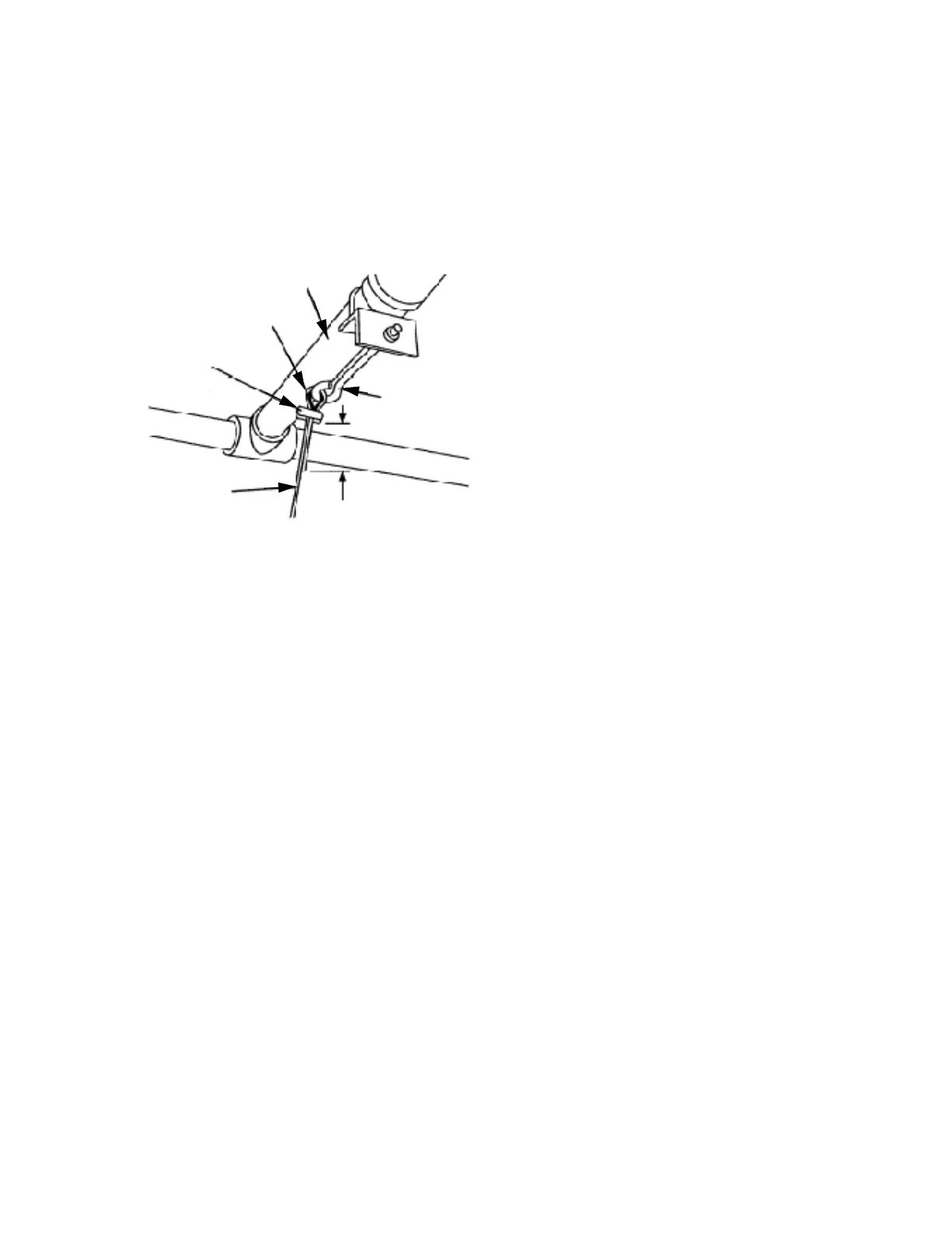
bolts (see Figure 7-5).
4. Pull cable ends out of inner roller brackets (see
Figure 7-6).
5. From service side, pull cable ends through brass
caps and outer roller brackets.
6. Unwind cable from capstan and pull entire length
of cable out of holes in capstan.
7. Remove limit switch actuator block clamped to
cable and discard cable.
• Prepare for new cable installation as follows:
1. Position carriage to approximate center of wash
chamber.
2. Loosen drive clutch by loosening adjusting nut
located in center of capstan (refer to Section 7.5.1,
Adjusting Carriage Drive Clutch).
3. Turn capstan until holes are facing cabinet.
Retighten drive clutch.
4. Remove brass caps, located in wash chamber, from
service side cabinet wall.
• Install new cable as follows:
1. With cable ends tightly wrapped with tape, thread
cable through holes in capstan. Pull approximately
half of cable through capstan.
2. Facing capstan, take right half of cable and make
three revolutions around capstan (downward on
capstan) by passing under cable protruding to left
(see Figure 7-7).
3. Working with right half of cable, feed cable through
limit switches and around outer roller bracket (see
Figure 7-6). Insert cable through cabinet opening
and install brass cap. Feed cable around inner roller
bracket and pull cable six inches past first carriage
eye bolt.
4. Thread cable through eye bolt and clamp cables as
close to eye bolt as possible allowing approximately
four inches of cable to extend past clamp.
5. Insert cable guard between cable and eye bolt to
prevent wear on cable.
6. With carriage centered, work cable back through
drive system until cable is semi-tight and lays in
grooves of capstan.
7. Working with cable protruding to left of capstan,
make two revolutions around capstan spiraling
upward. Feed cable around outer roller bracket and
through cabinet opening. Install brass cap and feed
cable around inner roller bracket. Pull cable tight.
8. Thread cable through eye bolt and clamp cable as
close to eye bolt as possible. Cut off excess cable
leaving approximately four inches of cable extend-
ing past clamp. Tightly wrap end of cable with tape
to prevent unraveling.
9. Insert cable guard between cable and eye bolt.
10.With carriage centered in wash chamber, attach
limit switch actuator block to drive cable, half way
between limit switches.
11.Evenly tighten eye bolts to remove slack from cable.
NOTE: Cable should remain slack enough to allow
limit switch actuator block one inch movement up
or down from center.
Figure 7-5. Carriage Eye Bolt
Carriage
Eye Bolt
Cable Guard
Cable Clamp
Drive Cable
4" (100 mm)




 To Next Page