147
DEFRNLIT EN
0478 131 9965 A - EN
– Position of the wire connectors
After a short while, the wire connectors
used are no longer visible. Their
position should be noted in order to
replace them as required. (Ö 12.16)
12.3 Routing the perimeter wire
● Install the docking station. (Ö 9.8)
● Route the perimeter wire around the
mowing area and any obstacles
beginning at the docking station
(Ö 12.9) and fasten it to the ground
using fixing pins. Check the clearances
using the iMOW® Ruler. (Ö 12.5)
Follow the instructions in the "Initial
installation" section. (Ö 9.9)
● Connect the perimeter wire. (Ö 9.10)
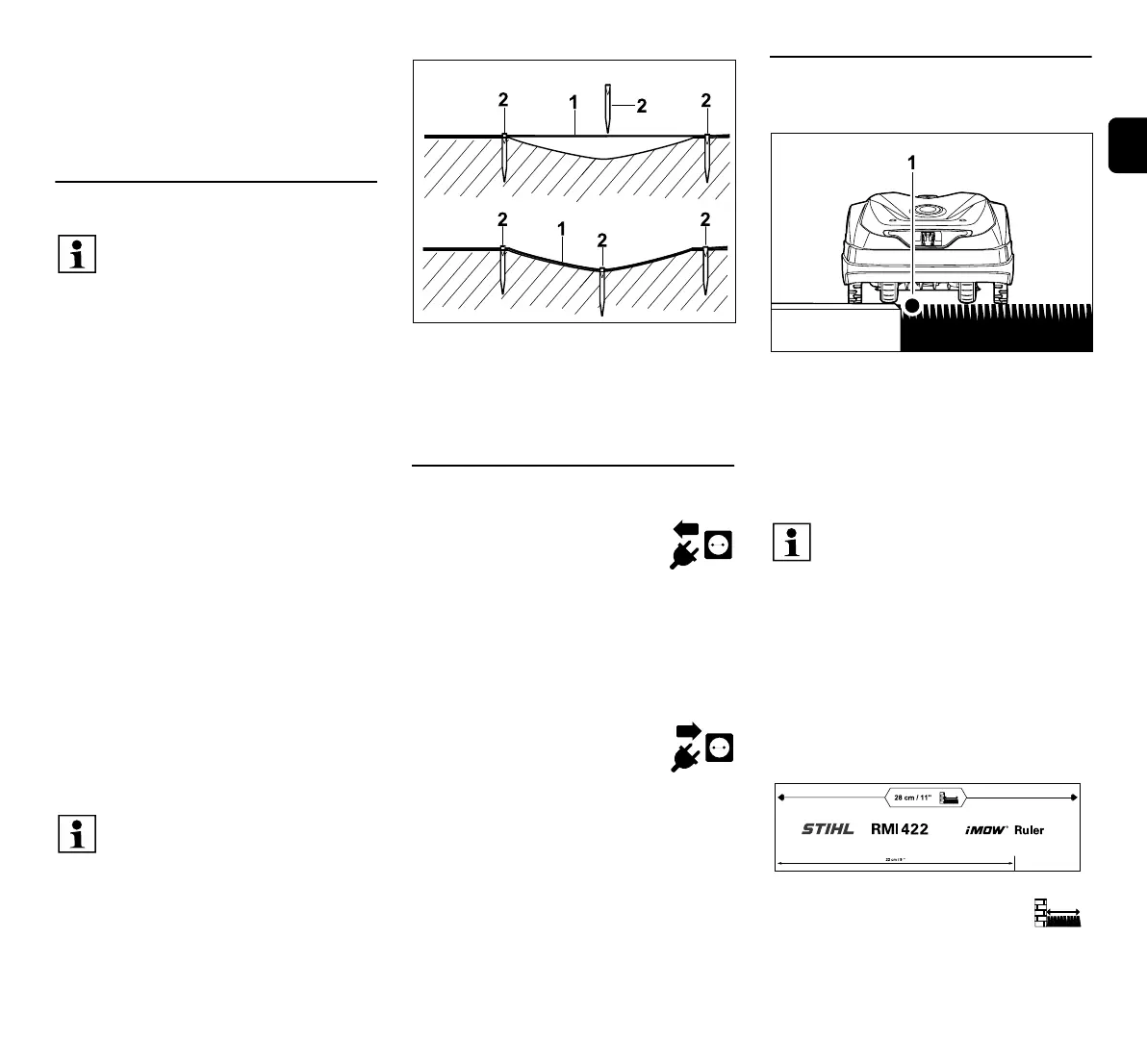
The perimeter wire (1) is routed above
ground and attached with additional fixing
pins (2) in case of unevenness. This
prevents the wire being cut by the mowing
blade.
12.4 Connecting the perimeter wire
● Disconnect the mains plug
and then remove the docking
station cover.
● Insert the perimeter wire into the cable
guides of the floor plate, guide it
through the socket, strip the ends and
connect to the docking station.
Follow the instructions in the "Initial
installation" section. (Ö 9.10)
● Install the docking station
cover and then connect the
mains plug.
● Check the wire signal. (Ö 9.11)
● Check docking. (Ö 15.6)
If necessary, correct the position of the
perimeter wire in the area of the
docking station.
12.5 Wire clearances – use
iMOW® Ruler
The perimeter wire (1) can be routed
without clearance along obstacles that
can be travelled on such as patios and
paths. The robotic mower then travels with
one rear wheel outside the mowing area.
Maximum stepped area to the turf: +/-
1cm
Measuring wire clearances with the
iMOW® Ruler:
To ensure the correct clearance from the
perimeter wire to the edge of the lawn and
to obstacles, the iMOW® Ruler should be
used for measuring the distances.
High obstacle:
Clearance between a high
obstacle and the perimeter wire.
Only use genuine fixing pins and
genuine perimeter wire.
Installation kits with the necessary
installation material are available as
an accessory from the STIHL
specialist dealer. (Ö 18.)
The routing direction (clockwise or
counterclockwise) is freely
selectable according to
requirements.
Never pull out fixing pins using the
perimeter wire – always use a
suitable tool (e.g. universal pliers).
Make a sketch of the perimeter wire
routing. (Ö 12.2)
Note:
Avoid excessive tensile stress on
the perimeter wire to prevent wire
breaks. In particular when using a
wire routing machine, make sure
that the perimeter wire unwinds
loosely from the spool.
Take care not to damage the
perimeter wire when tending to the
lawn edge. If necessary, install the
perimeter wire at a slight distance
(28 cm) from the lawn edge.
 Loading...