System Design
Overview of ftServer 2600, 4500, and 6300 Systems
1-5
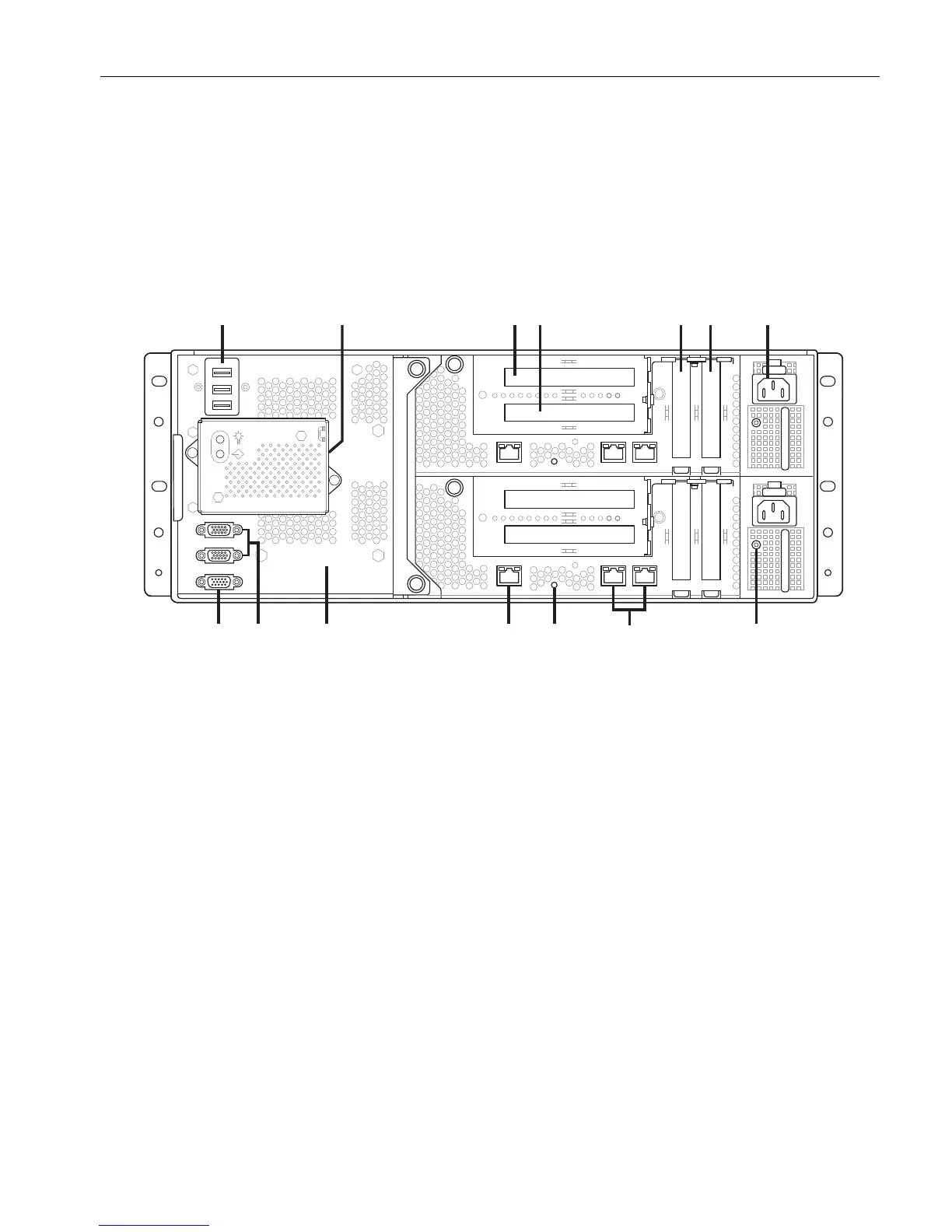
CPU-I/O Enclosures: Rear
Figure 1-3 shows a rear view of the CPU- I ⁄ O enclosures. See “Description of System
Components” on page 1-8 for a brief synopsis of some of the components identified in
the figure.
Figure 1-3. ftServer 2600, 4500, and 6300 Systems: Rear View
1 USB ports (3) 8 Power supply LED (2)
2 Modem and telephone port (on the side)
A modem is an optional component, so the
telephone port is not present if there is no
modem.
9 Ethernet ports (4)
3 PCI adapter slot 3 (PCIe or PCI-X). Not
available on ftServer 2600 systems.
10 CPU-I/O enclosure blue system
identifier LED (2)
4 PCI adapter slot 4 (PCIe or PCI-X). Not
available on ftServer 2600 systems.
11 VTM Ethernet port (2)
5 PCI adapter slot 1 (PCIe) 12 System backplane
6 PCI adapter slot 2 (PCIe) 13 Serial (COM) ports (2)
7 CPU-I/O enclosure power receptacle (2) 14 VGA (monitor) port
dco002b
12 34 567
911
10 81314 12