Status LEDs and System Buttons
Troubleshooting the Hardware
3-15
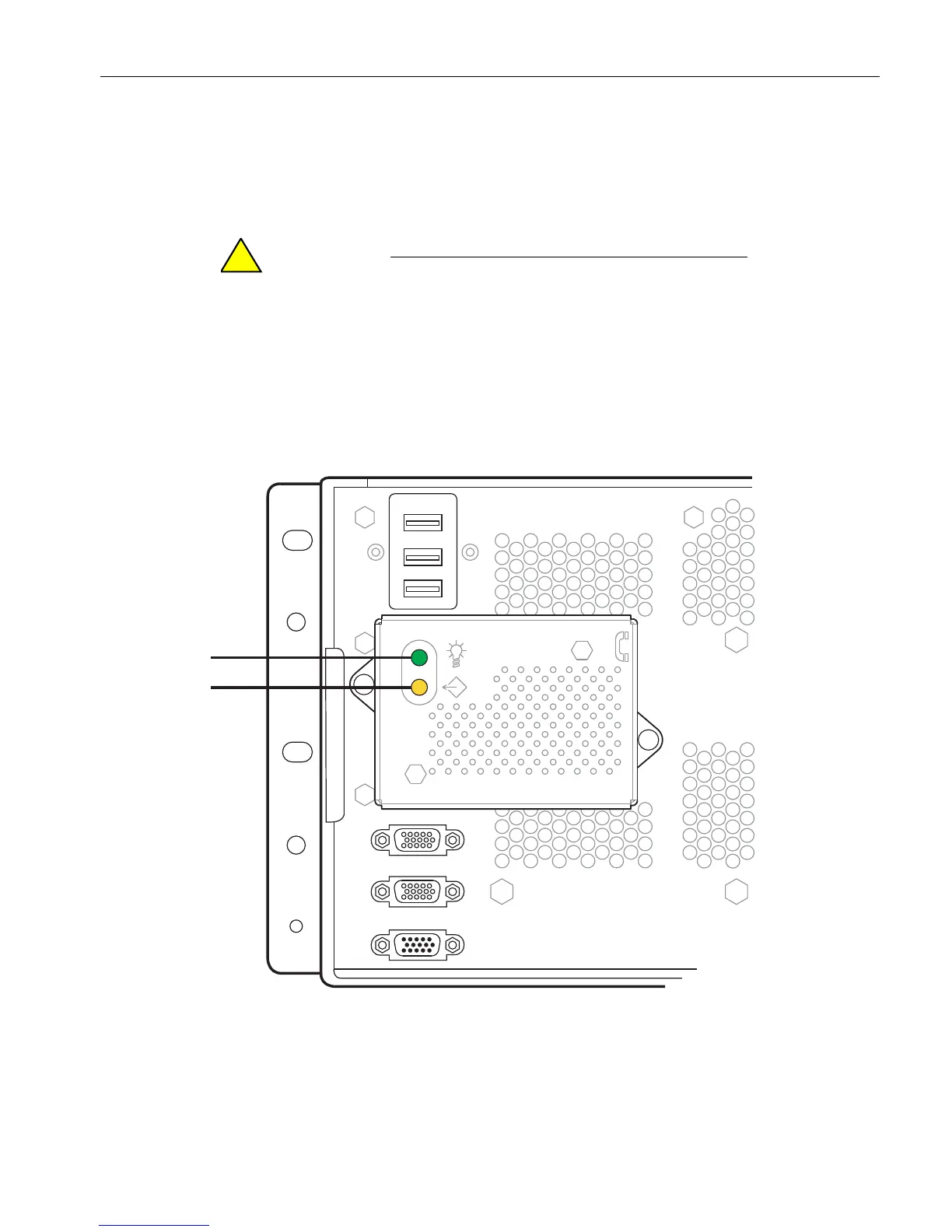
Figure 3-5 shows the modem-assembly status LEDs. Table 3 -7 describes the
modem-assembly LED states.
See your system administration documentation for information about component
failures and ways to correct them.
Do not remove the modem assembly when it is powered
on (steady green LED). For information about removing
and replacing a modem assembly, see “Replacing or
Installing a Modem Assembly” on page 5-48.
Figure 3-5. Modem Assembly: Status LEDs
1 Green LED (power indicator) 2 Yellow LED (fault or identifier indicator)