SummaCut User’s Manual
General Information 1-11
1. USB interface: - This interface is based on the standards specified in Universal
Serial Bus Specifications Revision 1.1. It allows a high-speed serial bi-
directional communication between the host computer and the cutter.
2. RS-232-C Port: - This DB-9P connector provides the communication link
between the cutter and a host computer. It allows bi-directional communication
between the host computer and the cutter.
3. Power ON/OFF switch - This rocker switch sets the cutter’s power to ON or
OFF. To switch the power ON, press the “I” side of the rocker switch. To switch
the power OFF, press the “O” side of the rocker switch.
4. Power Entry Module: - The fuse box and the AC power cord receptacle are
located in the power entry module.
The power-up procedure is explained in detail in Section 1.6.
5. Fuse box: - For information about changing of the fuse, see Section 4.2.
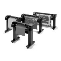
6. Roll Media Guide Bushes: - The two guide bushes serve to keep the media roll
in place when media is pulled from the roll.
7. Media Flanges: - The media flanges ensure proper routing of the media roll.
8. Media Support Roller: - Rotating support rollers for the media roll.
9. Alignment Strip: - Rear alignment strip for easier media loading.
 Loading...