SummaCut User’ s Manual
Interface 5-2
To set up your system, proceed as follows:
1. Press the “Start” Button and select “Settings”, continued by “Control Panel”. Press
on the “System” icon and select the “Device Manager” tab. Select the port that is
connected to the cutter and click on the properties button. Select the “Port Settings”
tab to set the port settings.
2. The default settings of the cutter are as follow:
• Baudrate : 9600 (see 2.3.8.)
• Data Bits : 8
• Parity : none (see 2.3.9.)
• Stop Bits : 2
• Flow Control : Hardware or Xon / Xoff
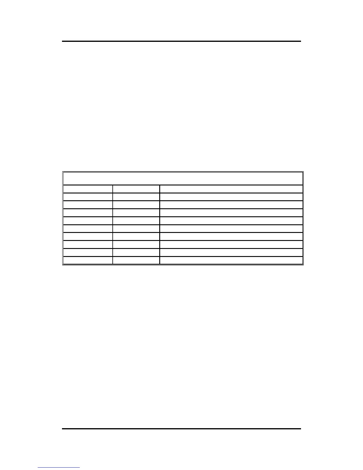
5.2.2 SERIAL INTERFACE CONNECTOR ON THE CUTTER
RS-232C Serial Interface Connector
Pin n° Signal Description
1 NC Not Connected
2 RXD Receive Data
3 TXD Transmit Data
4 DTR Data Terminal Ready
5 GND Signal ground
6 NC Not connected
7 RTS Request To Send
8 CTS Clear To Send
9 NC Not Connected
5.2.3 AVAILABLE SERIAL SIGNALS
If you are making your own cable, only a few of the cutter pins will actually need to be
connected to the host computer. To ensure optimum results, the cable length should
not exceed 4.8 m (16 feet). It should be taken into account that your computer or
cutting software may also require additional loopback connections at the host
computer's end of the data cable.
• Connect the Transmit Data (TXD) pin of the computer to pin #2 of the cutter.
• Connect the Receive Data (RXD) pin of the computer to pin #3 of the cutter.
• For hardware handshaking, connect the Clear To Send (CTS) pin of the
computer to pin #4 or pin #7 of the cutter. Connect the Request To Send (RTS)
pin of the computer to pin #8 of the cutter.
• Connect the ground (GND) pin of the computer to pin #5 of the cutter.