EasyManuals Logo

Sun Microsystems StorEdge 3510 User Manual

Sun Microsystems StorEdge 3510
328 pages
To Next Page IconTo Next Page
To Previous Page IconTo Previous Page
Page #71 background imageLoading...
Page #71 background image
Chapter 4 Connecting Your Fibre Channel Array 4-17
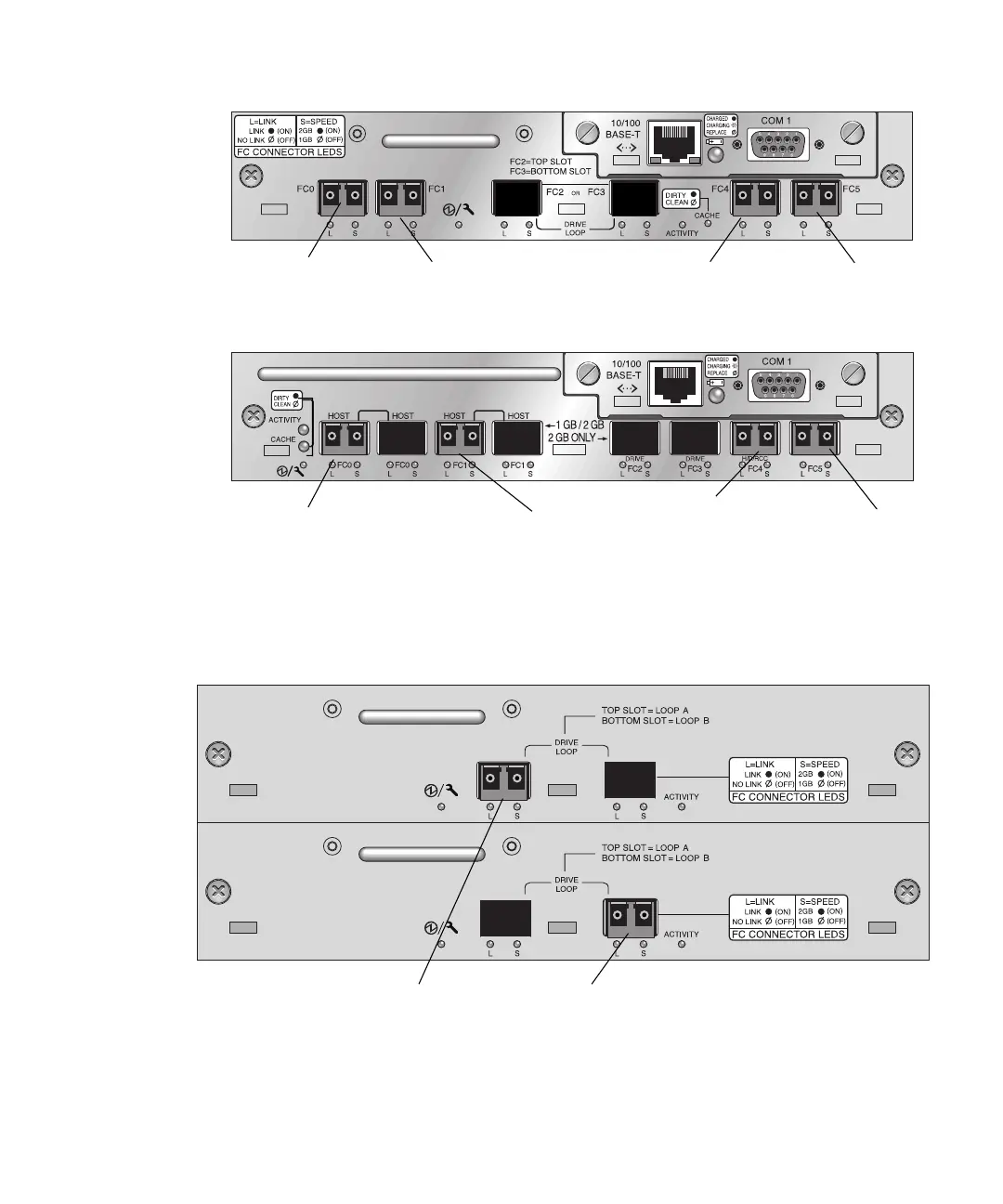
FIGURE 4-13 Sun StorEdge 3510 FC Array Default Single Controller SFP Placement
FIGURE 4-14 Sun StorEdge 3511 FC Array Default Single-Controller SFP Placement
In a default Sun StorEdge 3510 FC expansion unit, SFPs are initially plugged into the
left-most port of the upper I/O expansion module and right-most port of the lower
I/O expansion module (see
FIGURE 4-15).
FIGURE 4-15 Sun StorEdge 3510 JBOD/Expansion Unit Default SFP Placement
Host port FC0
Host port FC1
Host port FC4
Host port FC5
Host port FC1
H/D/RCC
Host port FC0
Host port FC4
Host port FC5
Default SFP Placement

Table of Contents

Other manuals for Sun Microsystems StorEdge 3510

Questions and Answers:

Question and Answer IconNeed help?

Do you have a question about the Sun Microsystems StorEdge 3510 and is the answer not in the manual?

Sun Microsystems StorEdge 3510 Specifications

General IconGeneral
BrandSun Microsystems
ModelStorEdge 3510
CategoryStorage
LanguageEnglish

Related product manuals