Appendix B Using a Standalone JBOD Array (Sun StorEdge 3510 FC Array Only) B-17
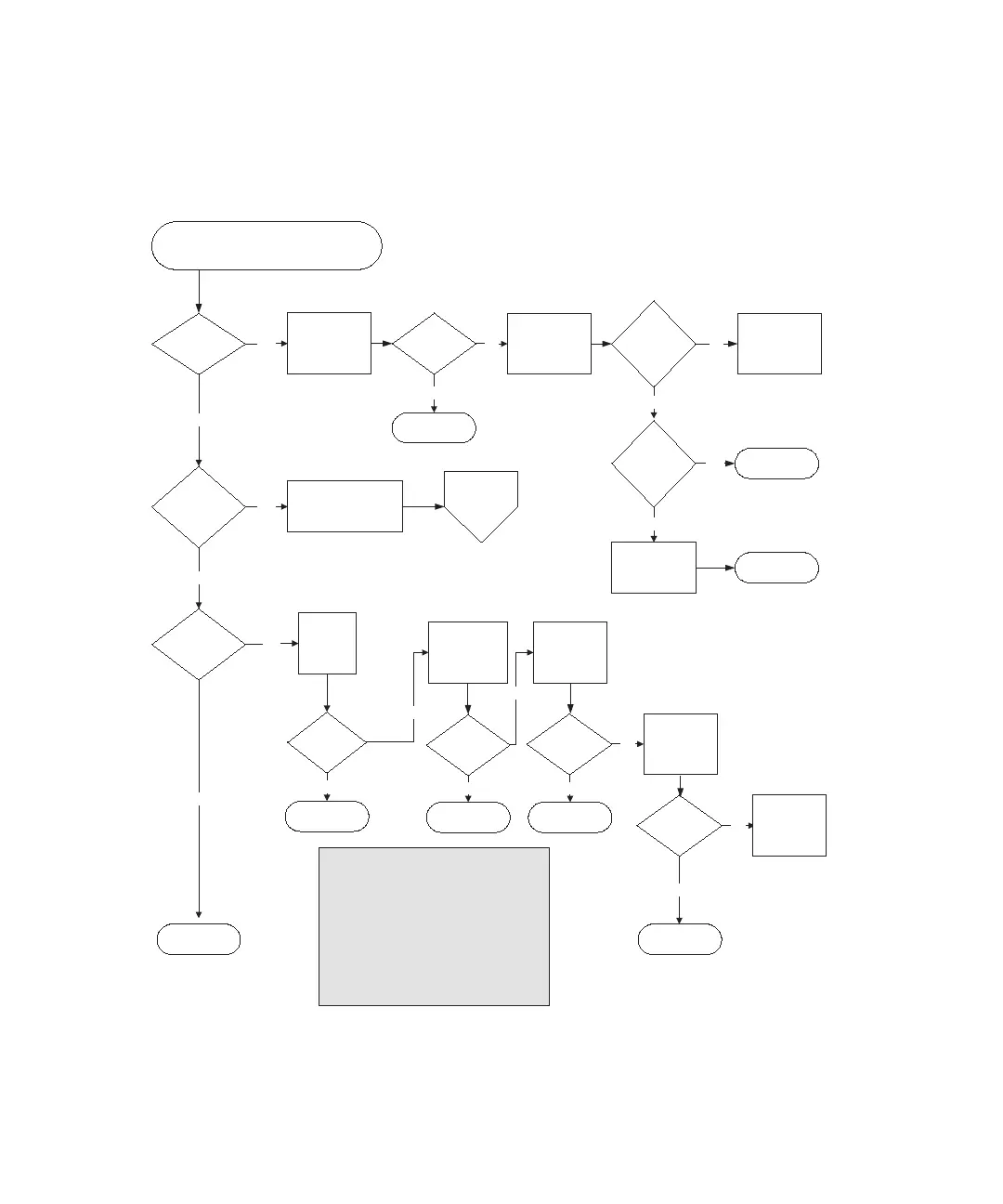
FIGURE B-4 JBOD or Expansion Unit Troubleshooting Flowchart, 1 of 2
Drive light
amber?
No
I/O expansion
module LED
amber
Ye s
SFP link status
amber?
Ye s
No
No
Ye s
Check event
messages in
firmware or software.
Replace chassis.
Switch drive with
known
drive from another
slot.
Replace drive
again.
Is the
drive light
green in new
slot?
Replace SFP
with
known good one.
Replace
cable.
Resolved?
End
Ye s
Check for
proper
cabling.
1
Resolved?
No
No
End
Ye s
5A
JBOD or expansion unit problem (FC)
2
Replace
drive with known-
good drive.
Resolved?
No
Ye s
No
Ye s
Resolved?
End
Ye s
Connect
to known
good HBA.
Resolved?
End
No
No
Replace I/O
expansion
module.
End
End
End
Go to 11B
Is the
drive light
green in the
original slot?
EndYe s
No
Ye s
--Reseat the FRU that is not operating correctly.
--Swap the questionable FRU with a known-good
FRU from the same array.
Notes
To check cabling, look for bent pins, loose wires,
loose cable shielding, or loose cable casing.
Fibre Channel arrays use SFP connectors to
attach the array to hosts and expansion units.
Each Fibre Channel I/O expansion module has
two SFP ports. These ports are labeled Loop A or
Loop B.
Prior to replacing a chassis, try the following: