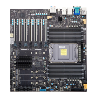
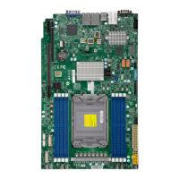
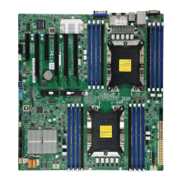
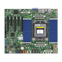
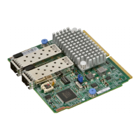
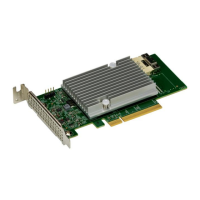
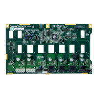
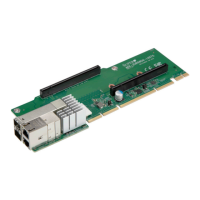
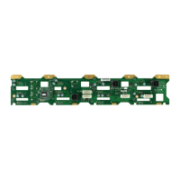
Figure 1-4. X14SAE-F Motherboard Layout
Notes:
l
See "Component Installation" on page 31 for detailed information on jumpers,
connectors, and LED indicators.
l
"■" indicates the location of pin 1.
l
Components not documented are for internal testing-purposes only.
l
Use only the correct type of onboard CMOS battery as specified by the manufacturer.
Do not install the onboard battery upside down to avoid possible explosion.
17
X14SAE/X14SAE-F: Introduction

 Loading...

