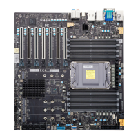
For a detailed diagram of the X14SAE/X14SAE-F motherboard, see the layout under "Quick
Reference" on page 13.
Internal Speaker/Buzzer
Pin Definitions: Two Total
Pin# Definition
1 Pos (+) Beep In
2 Neg (-) Alarm Speaker
M.2 M-Key PCIe 5.0/4.0 x4 Slots
Two M.2 M- key slots are located at M.2- C1 and M.2- P1 on the X14SAE/X14SAE- F
motherboard. Refer to the table below for more information.
Slots Signals Bus Interface Form Factors RAID Support
M.2-C1 From CPU PCIe 5.0 x4 2280 RAID 0 and 1
M.2-P1 From PCH PCIe 4.0 x4 2280 and 22110 RAID 0 and 1
Note: M.2-C1 and M.2-P1 slots can be mixed to support RAID 0 and 1.
For a detailed diagram of the X14SAE/X14SAE-F motherboard, see the layout under "Quick
Reference" on page 13.
Power LED Header
An onboard Power LED header is located at JLED1. This Power LED header is used to indicate
the status of system power.
For a detailed diagram of the X14SAE/X14SAE-F motherboard, see the layout under "Quick
Reference" on page 13.
Power LED Header
Pin Definitions: Three Total
Pin# Definition
1 POWER LED (+)
2 POWER LED (-)
3 POWER LED (-)
Power SMB (I²C) Header (X14SAE-F)
The Power System Management Bus (I²C) connector (JPI2C1 on the X14SAE-F motherboard)
monitors the power supply, fan, and system temperatures.
67
X14SAE/X14SAE-F: Component Installation

 Loading...

