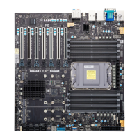
Quick Reference Table
Jumper Description Default
JBT1 Clear CMOS (Onboard) Short Pads to Clear CMOS
JD1 External Speaker/Buzzer
Pins 1–4: External Speaker
Pins 3–4: Buzzer (Default)
JPAC1 HD Audio Enable/Disable Pins 1–2 (Enabled)
JPCIESW CPU PCIe SLOT3 1x8/2x4
Pins 1–2: Slot3 1x8 (Default)
Pins 2–3: Slot3 2x4
JPG1 VGA Enable/Disable (X14SAE-F only) Pins 1–2 (Enabled)
JPL1, JPL2 LAN1/LAN2 Enable/Disable Pins 1–2 (Enabled)
JPME2 ME Manufacturing Mode Pins 1–2 (Normal)
JPT1 Onboard TPM 2.0 Enable/Disable Pins 1–2 (Enabled)
JWD1 Watchdog Function Enable Pins 1–2 (Reset)
LED Description Status
CATERR_
LED
Catastrophic Error LED Solid Orange: System CATERR
LEDBMC
X14SAE: Standby Power LED
X14SAE-F: BMC Heartbeat LED
X14SAE: Solid Green (Standby Power
On)
X14SAE-F: Blinking Green (BMC Normal)
LEDPWR Onboard Power LED Solid Green: Power On
UID
Unit Identifier (UID) LED (X14SAE-F
only)
Solid Blue: Unit Identified
Connector Description
12V_PUMP1 4-pin +12 V Power Connector (for CPU liquid cooling pump)
AUDIO Rear High Definition Audio Ports
18
X14SAE/X14SAE-F: Introduction

 Loading...

