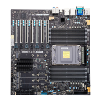
For a detailed diagram of the X14SAE/X14SAE-F motherboard, see the layout under "Quick
Reference" on page 13.
Power SMBus Header
Pin Definitions: Five Total
Pin# Definition
1 Clock
2 Data
3 PMBUS_Alert
4 GND
5 +3.3 V
Pump Power Header
The X14SAE/X14SAE-F motherboard has one +12 V header for optional CPU liquid cooling
systems. When using a liquid cooling system, attach the pump power cable to the 12V_PUMP1
header.
For a detailed diagram of the X14SAE/X14SAE-F motherboard, see the layout under "Quick
Reference" on page 13.
Pump Power Header
Pin Definitions: Four Total
Pin# Definition
1 GND (Black)
2 2A/+12 V (Red)
3 N/A
4 N/A
SATA 3.0 Ports
Eight Serial ATA (SATA) 3.0 ports (I- SATA0– I- SATA7) are supported on the
X14SAE/X14SAE-F motherboard. These I-SATA 3.0 ports are supported by the Intel PCH chip
(supporting RAID 0, 1, 5, and 10).
For a detailed diagram of the X14SAE/X14SAE-F motherboard, see the layout under "Quick
Reference" on page 13.
68
X14SAE/X14SAE-F: Component Installation

 Loading...

