UID Switch/HDD LED
The UID Switch (X14SAE-F only)/HDD LED connection is located on pins 13 and 14 of JFP1
on the motherboard. Attach a cable to pin 13 to use the UID switch. Attach a cable to pin 14 to
show storage drive activity status.
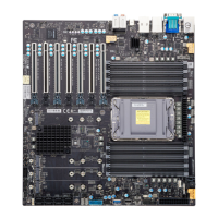
For a detailed diagram of the X14SAE/X14SAE-F motherboard, see the layout under "Quick
Reference" on page 13.
HDD LED/UID Switch
Pin Definitions (JFP1)
Pin# Definition
13 +3.3 V Stby/UID Switch
14 HDD Activity
Power LED
The Power LED connection is located on pins 15 and 16 of JFP1 on the X14SAE/X14SAE-F
motherboard.
For a detailed diagram of the X14SAE/X14SAE-F motherboard, see the layout under "Quick
Reference" on page 13.
Power LED
Pin Definitions (JFP1)
Pin# Definition
15 +3.3 V
16 PWR LED
NMI Button
The non-maskable interrupt (NMI) button header is located on pins 19 and 20 of JFP1 on the
X14SAE/X14SAE-F motherboard.
For a detailed diagram of the X14SAE/X14SAE-F motherboard, see the layout under "Quick
Reference" on page 13.
61
X14SAE/X14SAE-F: Component Installation

 Loading...

