4. Short the CMOS pads, JBT1, with a metal object such as a small screwdriver for at least
four seconds.
Note: Clearing CMOS will also clear all passwords.
5. Remove the screwdriver (or shorting device).
6. Replace the cover, reconnect the power cord(s), and power on the system.
CPU PCIe SLOT3 1x8/2x4
Use JPCIESW to configure the bifurcation mode for SLOT3. When changing the SLOT3
bifurcation mode, the SLOT6 bifurcation will also be changed. Refer to the table below for
jumpers settings and bifurcation modes between SLOT3 and SLOT6.
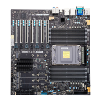
For a detailed diagram of the X14SAE/X14SAE-F motherboard, see the layout under "Quick
Reference" on page 13.
JPCIESW Jumper Settings PCIe SLOT3 PCIe SLOT6
Pins 1–2 1x8 (Default) Not populated 1x16
Pins 1–2 1x8 (Default) Populated 1x8
Pins 2–3 2x4 Not populated 1x8
Pins 2–3 2x4 Populated 1x8
External Speaker / Buzzer
On the JD1 header, close pins 3 and 4 with a cap to use the onboard buzzer. If you wish to use
an external speaker, close pins 1-4 with a cable.
For a detailed diagram of the X14SAE/X14SAE-F motherboard, see the layout under "Quick
Reference" on page 13.
External Speaker/Buzzer
Jumper Settings
Pin# Definition
Pins 1–4 External Speaker
Pins 3–4 Buzzer (Default)
HD Audio Enable/Disable
Use JPAC1 to enable or disable HD Audio on the X14SAE/X14SAE-F motherboard. The
default setting is Enabled.
72
X14SAE/X14SAE-F: Component Installation

 Loading...

