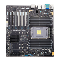
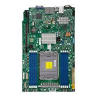
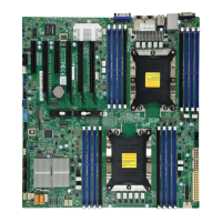
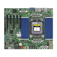
Connector Description
AUDIO FP
Front Audio Header
* The default setting is for a headphone/microphone combo jack. If not using a
chassis with the headphone/microphone combo jack, configure Frontside Audio
Mode in the BIOS Setup utility.
BMC_LAN Dedicated BMC LAN Port (X14SAE-F only)
BT1 Onboard Battery
COM1 COM Header
DP_HDMI DP: Rear DisplayPort 2.1. HDMI: High Definition Multimedia Interface 2.1
FAN1, FAN1A,
FAN2B, FANA
System Fan Headers
FAN2, FAN3,
FAN3C
CPU Fan Headers
I-SATA0–I-
SATA7
SATA 3.0 Ports (from Intel PCH, 6 Gb/sec, with support of RAID 0, 1, 5, and 10)
JFP1 Front Control Panel Header
JL1 Chassis Intrusion Header
JLED1 3-pin Power LED Indicator Header
JPI2C1 Power Supply SMBus I
2
C Header (X14SAE-F only)
JPW1 24-pin ATX Main Power Connector (Required)
JPW2 8-pin +12 V CPU Power Connector (Required)
JSD1 SATA Disk-On-Module (DOM) Power Connector
JSTBY1 Standby Power Header (5 V)
JTPM1 Trusted Platform Module (TPM)/Port 80 Header (TPM 2.0 only)
LAN1, LAN2
LAN1: RJ45 1 GbE LAN Port
LAN2: RJ45 2.5 GbE LAN Port
M.2-C1
PCIe 5.0 x4 M.2 M-key Slot (from CPU, with support of 2280 form factor)
* M.2-C1 and M.2-P1 can be mixed to support RAID 0 and 1.
M.2-P1
PCIe 4.0 x4 M.2 M-key Slot (from PCH, with support of 2280 and 22110 form factors)
* M.2-P1 and M.2-C1 can be mixed to support RAID 0 and 1.
19
X14SAE/X14SAE-F: Introduction

 Loading...

