APPENDIX B - PORTS
97
SG-System I Operating Manual
B
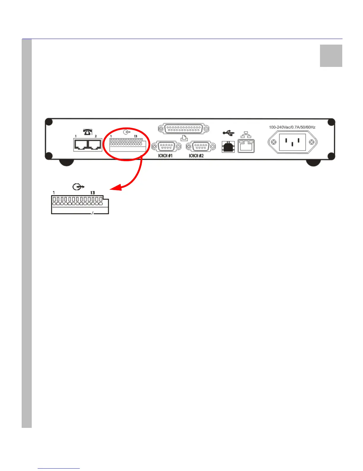
I/O Port
The I/O interface has access to the list of options below. These connections are located at the back of the unit using a screwless,
spring-type terminal. Relays are used for output-switching of the unit. There are three outputs and four inputs on the SG-Sys-
tem I unit.
Figure 11: I/O Ports
Note: Port numbers range from 1 to 13, from left to right.
See item 14 at Table 3: SG-System I Front and Rear Panel Descriptions on page 15 for a list and description of the I/O ports.
I/O Ports - Detailed Descriptions
Input 1 - PIN 1 - UPS AC Failure
• This input - normally closed - is used with backup power supplies that support output activation for the status indica-
tion. When this input is activated the SG-System I will indicate a trouble condition for UPS AC Fail. Debounce time on
this input is set at 250 msec. Debounce time is not programmable.
Input 2 - PIN 3 - UPS DC Failure
• This input - normally closed - is used with backup power supplies that support output activation for the status indica-
tion. When this input is activated the SG-System I will indicate a trouble condition for UPS DC Fail. Debounce time on
this input is set at 250 msec. Debounce time is not programmable.
Input 3 - PIN 4 - Remote Ack
• While the unit is in Manual mode, this option is used to provide the user with the means of acknowledging an alarm
condition from a remote location. The Remote Ack input will be available any time the front panel Ack button is available.
Debounce time on this input is set at 80 msec as will the front panel Ack button. The Remote Ack button must accept
depress and release before accepting the next depress.
Input 4 - PIN 6 - Reserved for Future Use
 Loading...


