PERIODIC MAINTENANCE 2-22
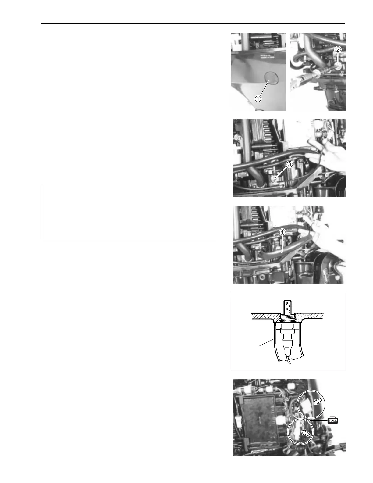
2. Remove grommet 1 and stbd.lower side cover.
(See page 7-1)
3. Remove plug 2 from oil pump case and install the O
2
sen-
sor 3 and protector sleeve 4.
18213-74F00 : O
2
sensor
18498-99E40 : Protector sleeve
B
The O
2
sensor used for the feedback test procedure
must be in proper working order and installed se-
curely.
If either sensor or installation is improper, the O
2
feed-
back operation will be performed incorrectly and
could possibly result in engine operating problems.
NOTE:
• The O
2
sensor is NOT WATERPROOF.
Cover O
2
sensor with the protector sleeve to protect from water
spray.
• Cut off the protector (P/N 18498-99E40) to a length of 20 –
30 cm (7.8 – 11.8 in.). The O2 sensor must be completely
covered as shown.
4. Connect the diagnostic harness to both O
2
sensor and en-
gine harness connectors.
09932-79910 : Diagnostic harness
z
z
4