6-22 POWER UNIT
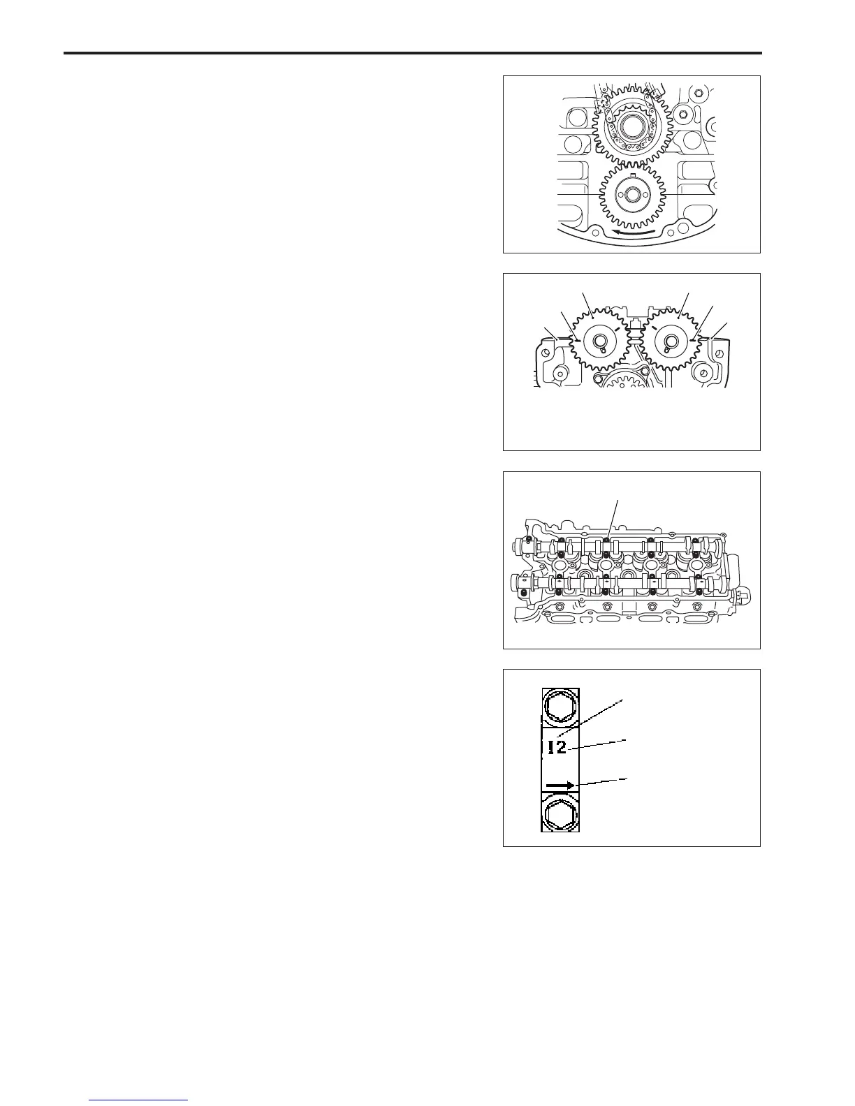
7. Install camshaft housing pins as shown in figure.
8. Check position of camshaft housing.
NOTE:
Embossed marks are provided on each camshaft housing indi-
cating position and direction of installation.
9. Install housings as indicated by these marks.
I : Intake side
E : Exhaust side
Position from flywheel
magneto side
Pointing to flywheel
magneto side
NOTE:
Before installing camshafts, turn crankshaft until No.1 cylinder
reaches top dead center. (See page 6-14)
NOTE:
When install camshaft, adjust relative position between sprock-
ets and chain so that match marks (dot) on timing sprockets
are as shown in figure and engraved lines on sprockets align
with cylinder head cover mating face.
1
1
2
2
3
3
1. Match mark (dot)
2. Match mark (engraved line)
3. Cylinder head cover mating face
Pin