3-42 ENGINE CONTROL SYSTEM
1 2 3 4 5 6 7 8 9 10
11
12
13
14
15
16
17
18
19
20
21
22
23
24
25
26
27
28
29
30
31
32
33
34
35
36
37
38
39
40
41
42
43
44
(White connector)
(Black connector)
1 2 3 4 5 6 7 8 9 10 11 12 13
14 15 16 17 18 19 20 21 22
23 24 25 26 27 28 29 30 31 32 33 34 35
36 37 38 39 40 41 42 43 44
Wire harness
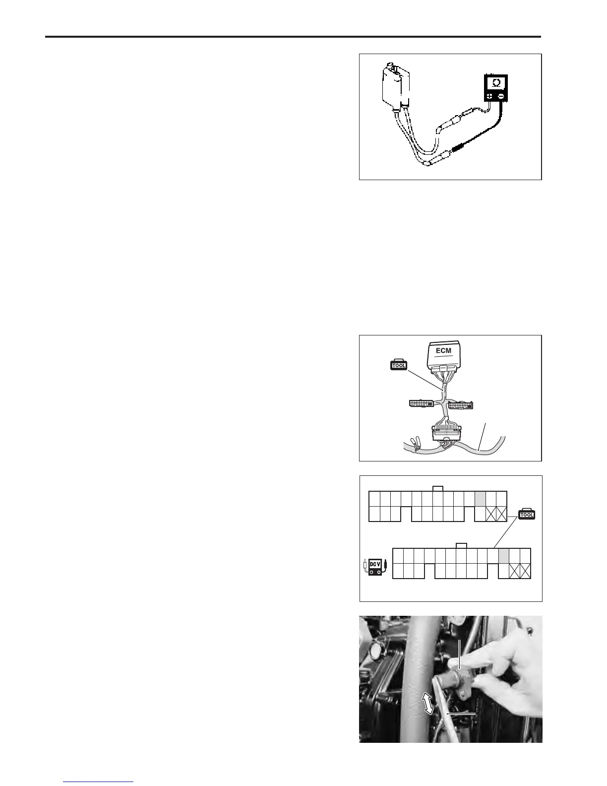
CMP SENSOR SIGNAL
\ 09930-89950 : 44-pin test cord
09930-99320 : Digital tester
U Tester range :
V (DC voltage)
1. Remove CMP sensor. (See page 3-53.)
2. Connect 44-pin test cord between ECM and wire harness
as shown in figure.
3. Connect tester probe + (Red) to No.33 terminal.
4. Connect tester probe - (Black) to No.11 terminal (or to
body ground).
5. Turn ignition switch ON.
6. Measure voltage when steel tip of a screwdriver is brought
near and then pulled away from sensor tip.
CMP sensor signal : Approx. 0.3V or 5V
IGNITION SECONDARY COIL RESISTANCE
\ 09930-99320 : Digital tester
V Tester range :
Ω Ω
Ω Ω
Ω (Resistance)
1. Disconnect spark plug caps from spark plugs.
2. Measure resistance between both spark plug caps as shown
in figure.
Ignition secondary coil resistance :
No. 2&3 18 – 34 k
ΩΩ
ΩΩ
Ω
No. 1&4 19 – 36 k
ΩΩ
ΩΩ
Ω
NOTE:
Two signal voltages mentioned above (0.3V or 5V) will
change by repeating movement of screwdriver.
1
2
1
2
1. Screwdriver
2. CMP sensor
1. Screwdriver
2. CMP sensor
 Loading...


