ENGINE CONTROL SYSTEM 3-43
MAP SENSOR OUTPUT VOLTAGE CHANGE
\ 09917-47011 : Vacuum pump gauge
09930-89950 : 44-pin test cord
09930-99320 : Digital tester
U Tester range :
V (DC voltage)
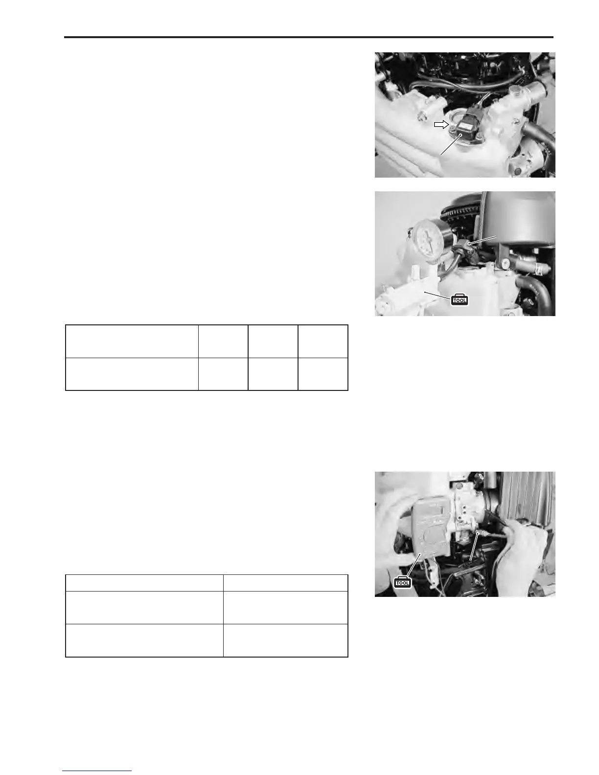
1. Remove bolts and MAP sensor from intake manifold.
2. Connect vacuum pump gauge (with hose) to MAP sensor
as shown in figure.
3. Turn ignition switch ON.
4. While applying negative pressure (vacuum) to MAP sen-
sor, measure “29” terminal voltage. (See page 3-36 and 3-
37 for procedure)
MAP sensor output voltage change :
Negative pressure
kPa (kg/cm
2
, mm Hg)
“29” terminal
voltage (
V
)
0
(0, 0)
40
(0.4, 300)
80
(0.8, 600)
4.00
2.42 0.84
(at 1013 hPa barometric pressure)
\ 09930-99320 : Digital tester
T Tester range :
@@
@@
@ (Continuity)
1. Disconnect CTP switch wire.
2. Inspect continuity between CTP switch terminal and body
ground.
Throttle position Continuity
Fully closed
(switch contact in)
Ye s
Not fully closed
(switch contact out)
No
CTP switch function :
CTP SWITCH