3-44 ENGINE CONTROL SYSTEM
ECM main relay
12V
OIL PRESSURE SWITCH
\ 09940-44121 : Air pressure gauge
09952-99310 : Air pump
T Tester range :
@@
@@
@ (Continuity)
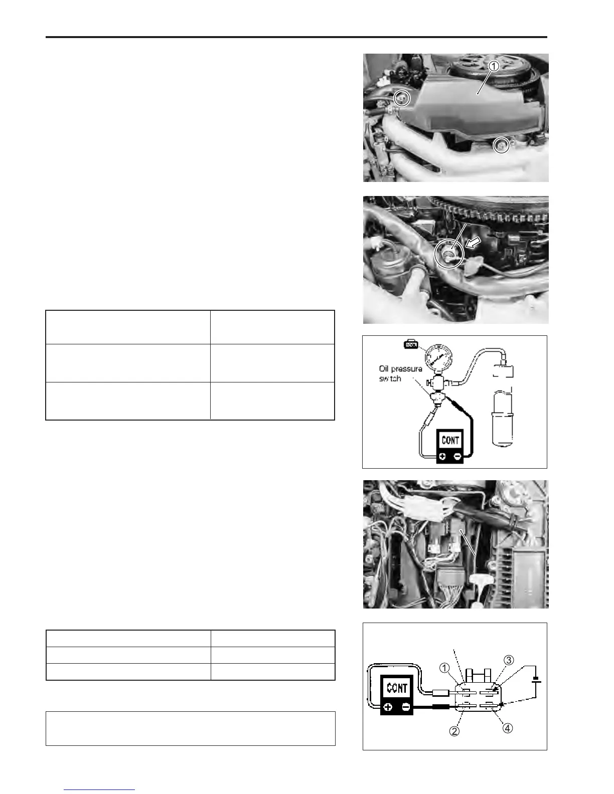
1. Remove bolts and air duct 1.
2. Remove oil pressure switch. (See page 3-54)
3. Connect the gauge and pump as shown in figure.
4. While applying pressure to oil presure switch, inspect con-
tinuity between, switch body and switch terminal bolt as
shown in figure.
ECM MAIN RELAY
\ 09930-99320 : Digital tester
T Tester range :
@@
@@
@(Continuity)
1. Disconnect ECM main relay from wire harness.
2. Inspect continuity between terminal 1 and 2 each time
12V is applied. Connect positive + side to terminal 4, and
negative - side to terminal 3.
ECM main relay function :
12 V power Continuity
Applied Yes
Not applied No
Be careful not to touch 12 V power supply wires to each
other or with other terminals.
ECM main relay function :
Oil pressure switchOil pressure switch
ECM main relayECM main relay
Pressure
kPa (kg/cm
2
)
Continuity
Less than
70 – 130 (0.7 – 1.3)
Ye s
No
70 – 130 (0.7 – 1.3)
or over