SYNRAD FH Series Flyer Operator’s Manual Version 3.4
96
Tracking hardware
Encoder connection
Encoder outputs are connected directly to FH Flyer’s DB-25 User Interface connector. If you are using a
unidirectional (single output) encoder, connect your wiring as shown for ‘A’ phase (øA) in the following
diagrams.
T
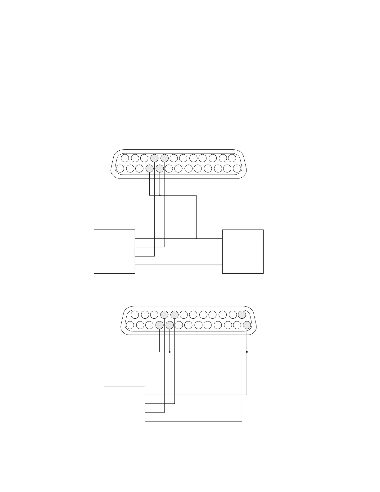
o connect a position encoder, refer to the appropriate connection diagram. Figure 5-10 shows a
customer-supplied power supply driving a current-sinking NPN open collector encoder. Figure 5-11
shows how to power the same type encoder from Flyer’s built-in +15 VDC power supply. See Figure 5-12
or 5-13 when wiring current-sourcing PNP encoders.
25
24
15
14
13
12
2
1
DC POWER SUPPLYPOSITION ENCODER
V+
GND
V+
øA
øB
GND
22
9
IN1_HI
IN1_LO
IN2_HI
IN2_LO
21
10
Figure 5-10 Wiring diagram for current-sinking (NPN open collector) encoders
Figure 5-11
Wiring diagram for current-sinking (NPN open collector) encoders using
Flyer’s built-in power supply
25
24
15
14
13
12
2
1
POSITION ENCODER
9
IN1_HI
IN1_LO
IN2_HI
IN2_LO
+ 15 V
+ 15 RTN
21
V+
øA
øB
GND
22
10