tracking
SYNRAD FH Series Flyer Operator’s Manual Version 3.4
97
Tracking hardware
Fi
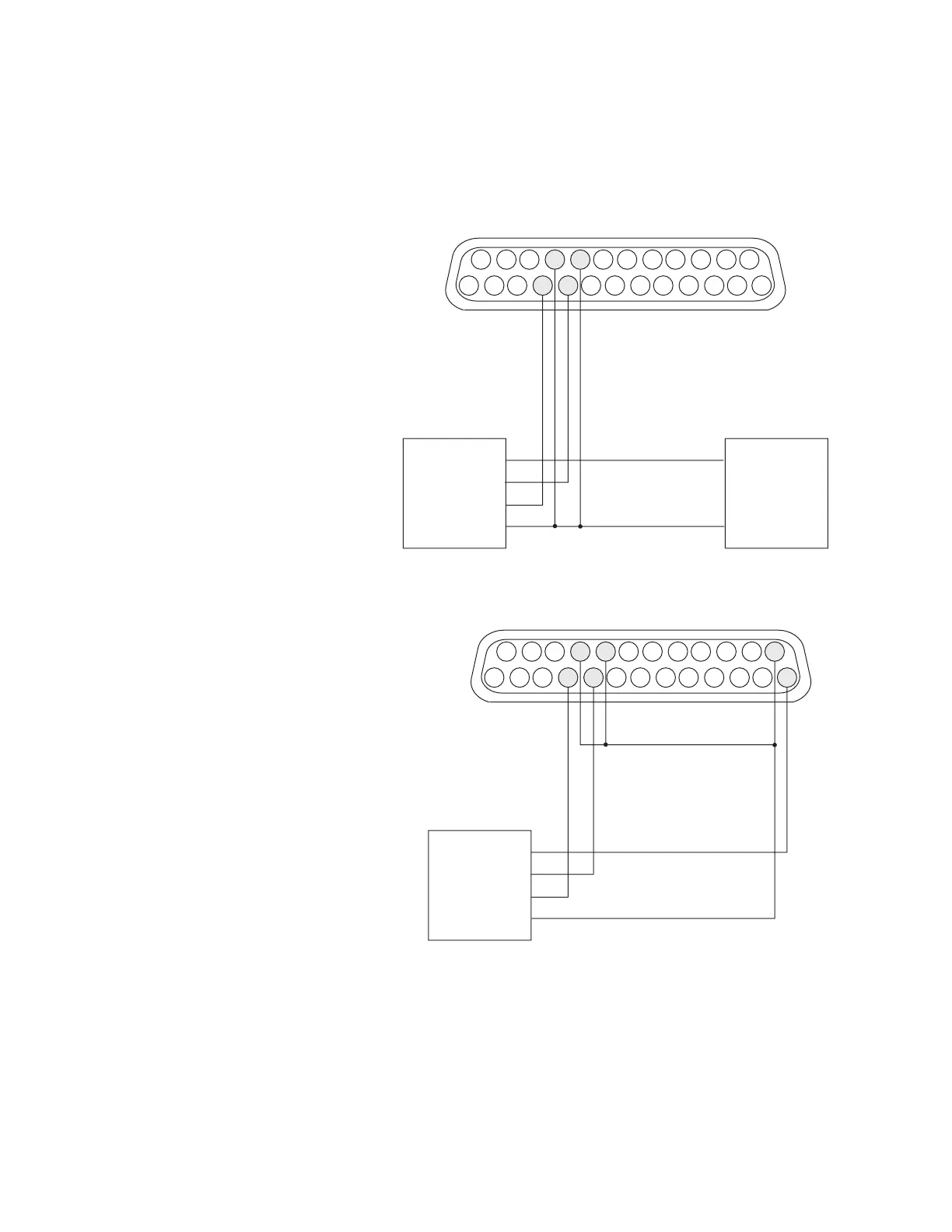
gure 5-12 shows a customer-supplied power supply driving a current-sourcing PNP open collector
encod-er. Figure 5-13 shows how to power the same type of encoder from Flyer’s built-in +15 VDC power
supply.
25
24
15
14
13
12
2
1
DC POWER SUPPLYPOSITION ENCODER
V+
GND
V+
øA
øB
GND
22
9
IN1_HI
IN1_LO
IN2_HI
IN2_LO
21
10
Figure 5-12 Wiring diagram for current-sourcing (PNP open collector) encoders
Figure 5-13 Wiring diagram for current-sourcing (PNP open collector) encoders using
Flyer’s built-in power supply
Verify that eld wiring is correct after all encoder connections are complete using the Digital Scope ap-
plication (DigScope.exe in the WinMark folder). If the encoder is properly connected, inputs IN1 and IN2
should toggle as the position encoder rotates through its range of motion.
25
24
15
14
13
12
2
1
POSITION ENCODER
V+
øA
øB
GND
22
9
IN1_HI
IN1_LO
IN2_HI
IN2_LO
+ 15 V
+ 15 RTN
21
10