SYNRAD FH Series Flyer Operator’s Manual Version 3.4
102
Tracking hardware
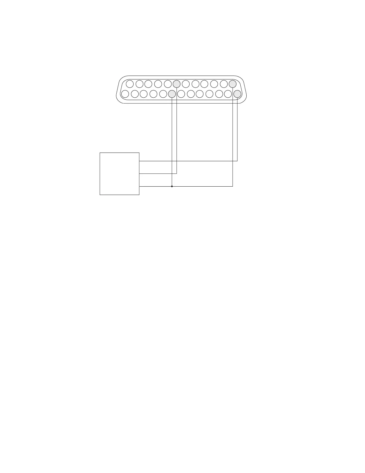
Figure 5-18 Wiring diagram for current-sourcing (PNP open collector) sensors using
Flyer’s built-in power supply
Verify that eld wiring is correct after all part sensor connections are complete using the Digital Scope
application (DigScope.exe in the WinMark folder). If the part sensor is properly connected, input IN0
should toggle when the part sensor activates.
25
24
15
14
13
12
2
1
PA RT SENSOR
V+
OUT
GND
8
IN0_A
IN0_B
+ 15 V
+ 15 RTN
20