technical reference
SYNRAD FH Series Flyer Operator’s Manual Version 3.4
125
–1.0 to +1.0 +3.0 to 24.0 6 9 16 23 20 29 32 47 1
IN0_A
IN0_B
IN1_HI
IN1_LO
IN2_LO
IN2_HI
IN3_A
IN4_A
IN5_A
IN6_A
IN7_A
IN3-7_B
Pin 8
Pin 9
Pin 21
Pin 22
Pin 10
Pin 23
Pin
11
Pin 24
Pin 12
Pin 25
Pin 13
50mA
750Ω, 2W
100mA
310Ω, 2W
309Ω, 1/8W
5.6V
1000pF
5.6V
1000pF
100mA
310Ω, 2W
309Ω, 1/8W
50mA
750Ω, 2W
50mA
750Ω, 2W
50mA
750Ω, 2W
50mA
750Ω, 2W
50mA
750Ω, 2W
Input eld wiring notes
In electrically noisy environments, we recommend using shielded multi-conductor I/O cable as well as
a shielded backshell when connecting eld wiring to Flyer’s DB-25 User Interface connector.
To minimize ground loop noise, ground the cable shield at the signal source only. The cable shield at
the User Interface connector must be left oating unless you are using Flyer’s +15 VDC auxiliary power
output as the I/O signal source.
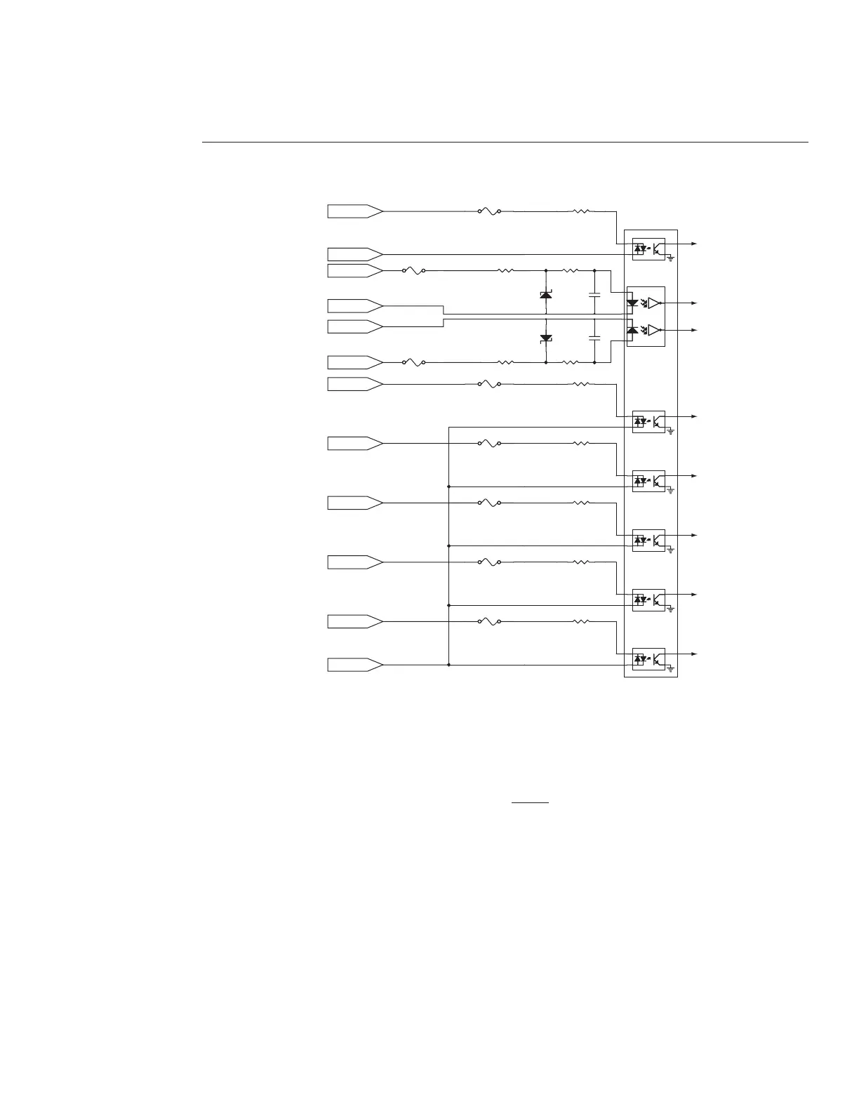
Input/Output circuitry
Figure 6-3 illustrates an equivalent circuit diagram of FH Flyer’s optically-isolated input circuitry.
Figure 6-3
FH Flyer’s equivalent input circuit