SYNRAD FH Series Flyer Operator’s Manual Version 3.4
126
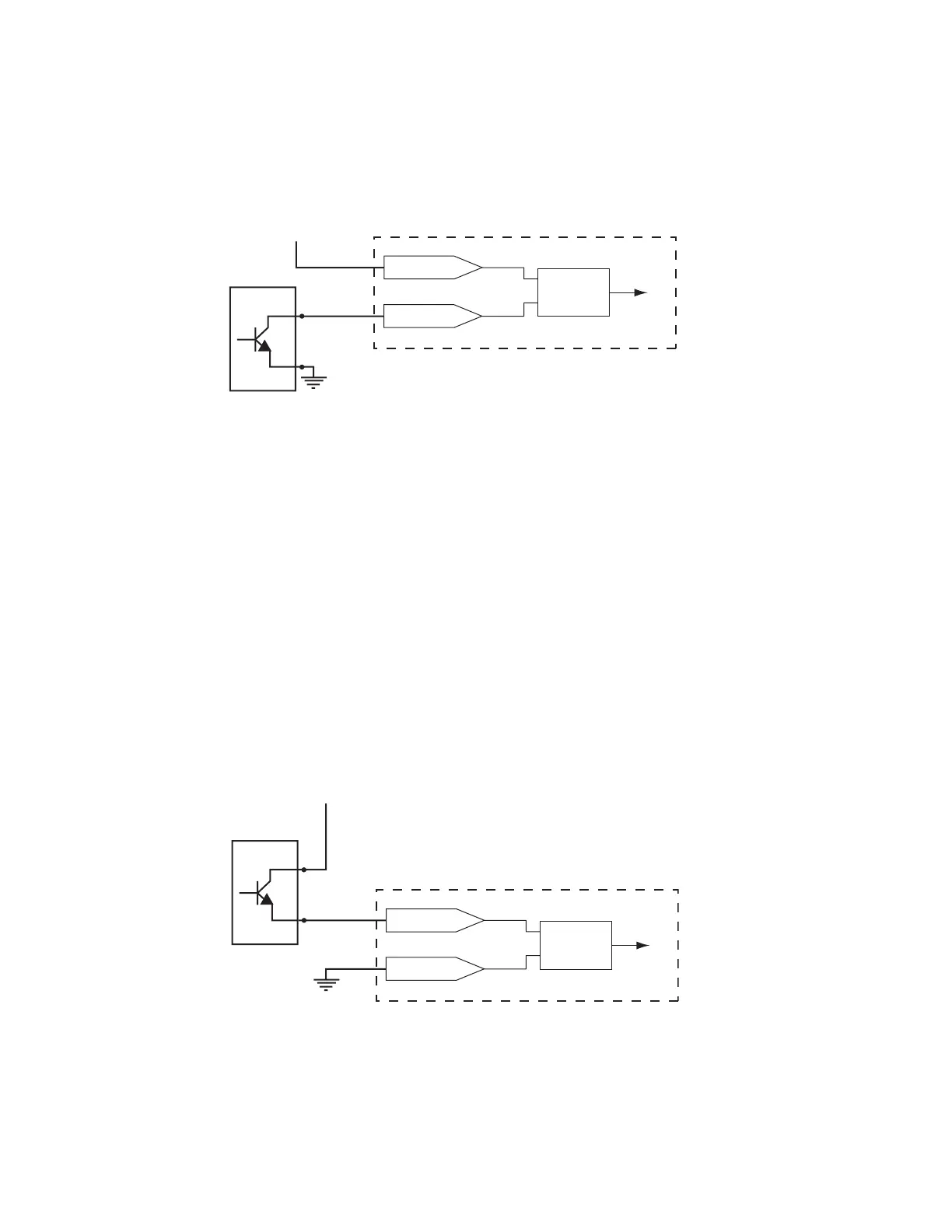
Sample input circuits
Flyer’s optically-isolated inputs are used to start the mark sequence or perform other functions based on
to
+ 24 VDC
NPN Open-Collector
Output Device
FH Flyer Input Section
IN3–7_B
IN3_A
Flyer Input
Circuitry
to
+ 24 VDC
NPN Open Emitter
Output Device
FH Flyer Input Section
IN3–7_B
IN3_A
Flyer Input
Circuitry
signals from external devices. When an external device sinks or sources current through an input, FH Flyer
senses a high-level state (1); when no current ows through the input, Flyer senses a low-level state (0).
FH Flyer inputs are designed for compatibility with standard industrial control circuit voltages in the
range from 5 V to 24 VDC. See Table 6-7 for a listing of possible input signal configurations.
From sinking NPN open collector device
Figure 6-4 illustrates one method of activating a Flyer input from an NPN open collector
logic device that is sinking current.
Input/Output circuitry
Figure 6-4 Activating Flyer input with a current sinking device
For example, to drive Flyer inputs from a PLC using an NPN open collector output module in
a current sinking conguration, connect the voltage source to IN3–7_B (the common re-
turn for inputs IN3_A through IN7_A) and connect each PLC output to Flyer inputs IN3_A
through IN7_A as required. This allows the PLC’s output module to independently activate
Flyer inputs by pulling individual inputs to ground. In Figure 6-4, Flyer input IN3 is
activated when input IN3_A is pulled to ground by the corresponding PLC output. See
Table 6-7 for a listing of possible input signal configurations.