technical reference
SYNRAD FH Series Flyer Operator’s Manual Version 3.4
127
to
Relay Contact
or
Foot Switch
FH Flyer Input Section
IN0_A
IN0_B
Flyer Input
Circuitry
to
+ 24 VDC
Relay Contact
or
FH Flyer Input Section
IN0_A
IN0_B
Flyer Input
Circuitry
From sourcing NPN open emitter
device
Figure 6-5 illustrates a circuit for activating a Flyer input from an NPN open emitter logic
device that is sourcing current.
Figure 6-5 Activating Flyer input with a current sourcing device
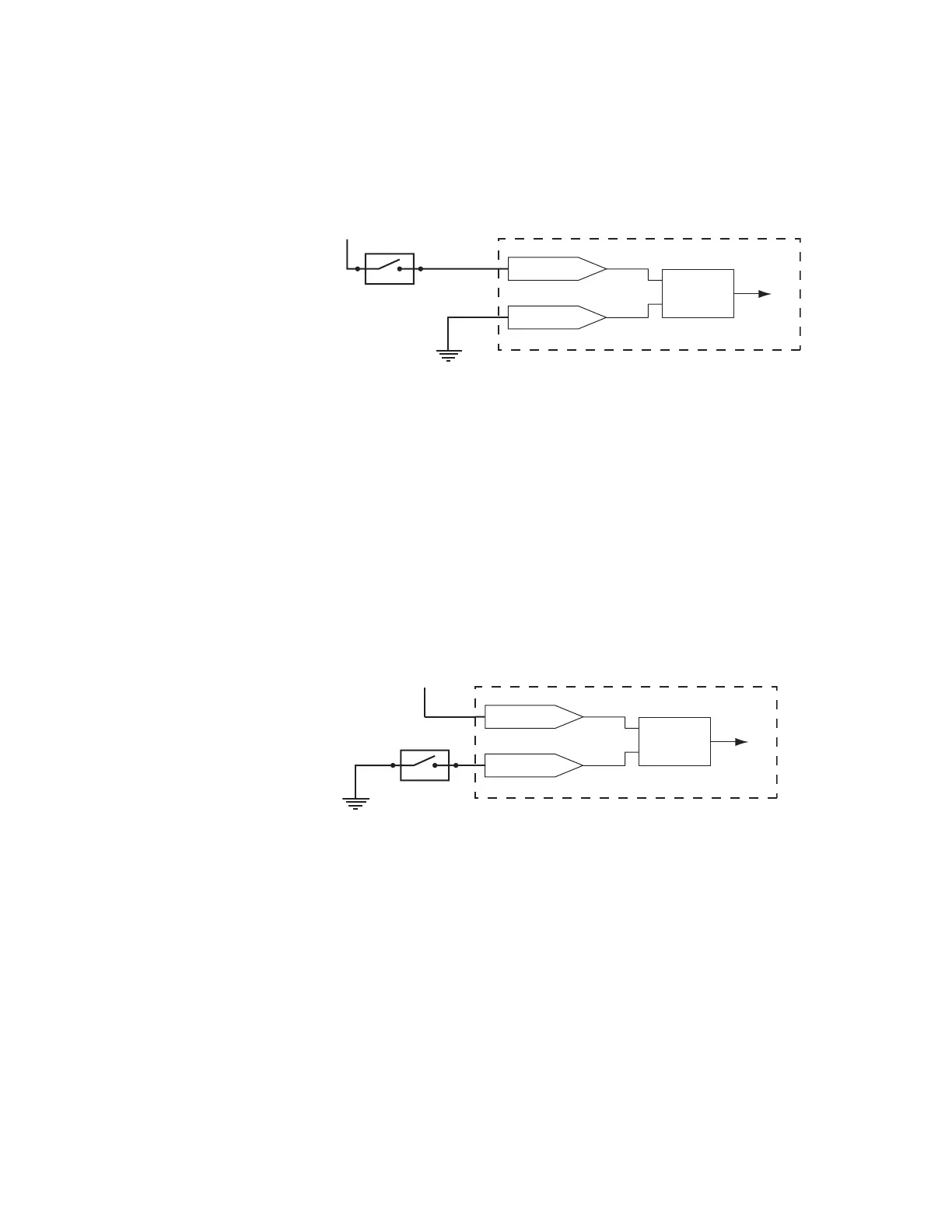
From switch or relay contact
Another common requirement in marking applications is for an operator to initiate each
mark operation by closing a foot-operated switch. Figure 6-6 illustrates a simple current
sourcing cir-cuit for using a foot switch or relay contact to send an input signal to the Flyer
marking head.
Input/Output circuitry