SYNRAD FH Series Flyer Operator’s Manual Version 3.4
128
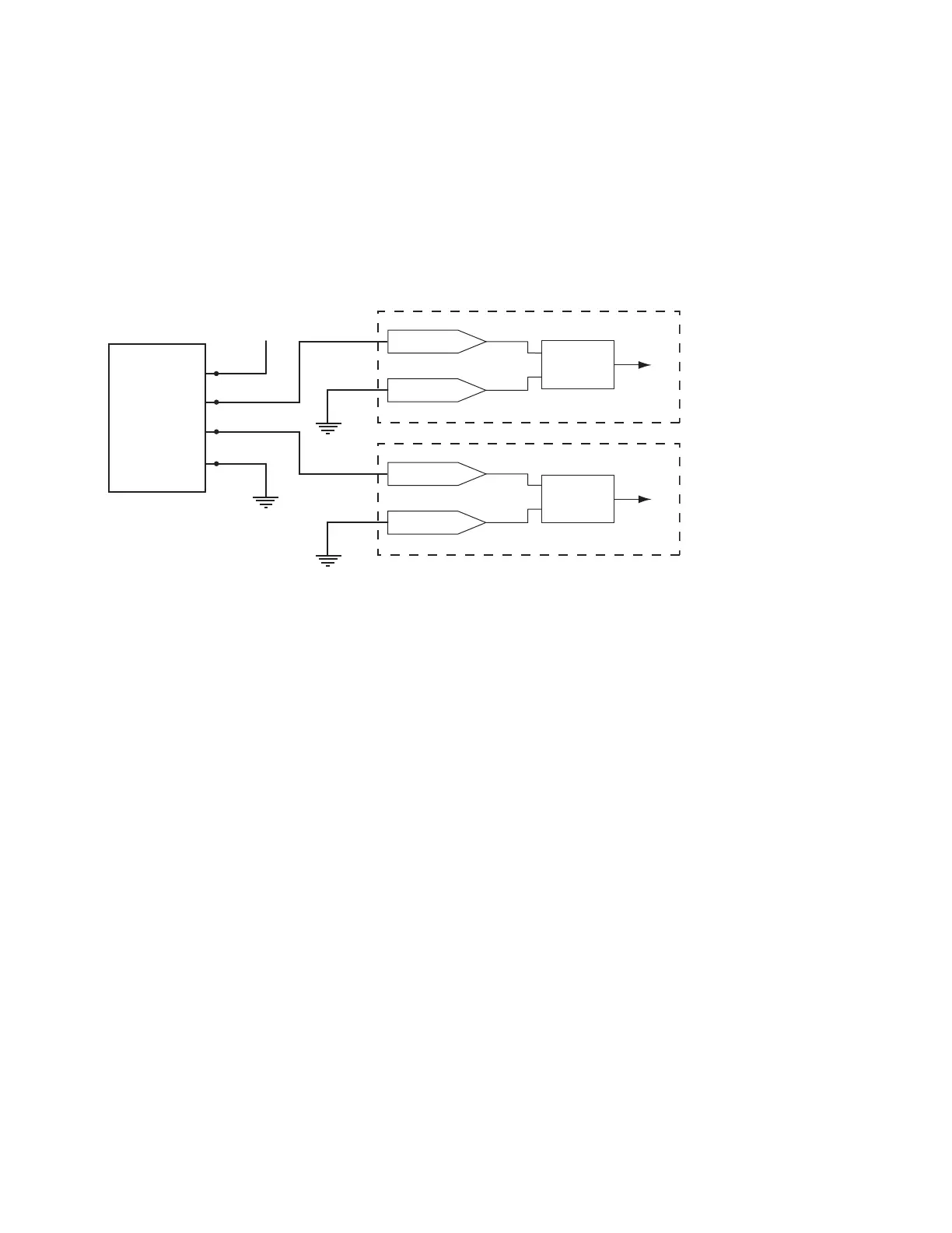
Figure 6-6 Driving Flyer from current sourcing switch or relay device
For example, to use a foot switch or relay contact wired in a current sourcing conguration to
initiate marking, connect your voltage source to one side of the Normally Open (NO) contact
and connect the other side of the NO contact to IN0_A. Connect IN0_B back to the power
supply’s return connection to complete the circuit. Because IN0 is a bipolar input you could
+ 5.0 V
to
+ 24 VDC
IN1_HI
IN1_LO
IN2_HI
IN2_LO
Position Encoder
V+
ØA
ØB
GND
Flyer Input
Circuitry
Flyer Input
Circuitry
instead connect the output of the foot switch to IN0_B and ground IN0_A depending on
your wiring scheme. See Table 6-7 for a listing of possible input signal configurations.
Figure 6-7 illustrates the same foot switch or relay contact device connected in a current
sink-ing configuration.
Figure 6-7 Driving Flyer from current sinking switch or relay device