technical reference
SYNRAD FH Series Flyer Operator’s Manual Version 3.4
131
T
able 6-9 FH Flyer output signal parameters
Output Parameter Specication
from CPU
from CPU
OUT0_A
OUT0_B
OUT1_A
OUT1_B
OUT2_A
OUT3_A
OUT4_A
OUT5_A
OUT6_A
OUT7_A
OUT2-7_B
+15 VDC
Pin 7
Pin 6
Pin 5
Pin 4
Pin 3
Pin 2
Pin 1
15 V RTN
500mA
+ Vs
50mA
900Ω, 2W
680pF
50mA
900Ω, 2W
680pF
50mA
900Ω, 2W
680pF
50mA
900Ω, 2W
680pF
50mA
900Ω, 2W
680pF
680pF
50mA
900Ω, 2W
680pF
50mA
900Ω, 2W
680pF
DC – DC
Convertor
Sinking/Sourcing Current, max. 30 mA
Load Voltage, max. 26 VDC
Output Impedance (On state) ~900 Ohms
Turn-On Time, max. 3.0 ms
Turn-O Time, max. 0.2 ms
O State Leakage Current, max. 1.0 µA
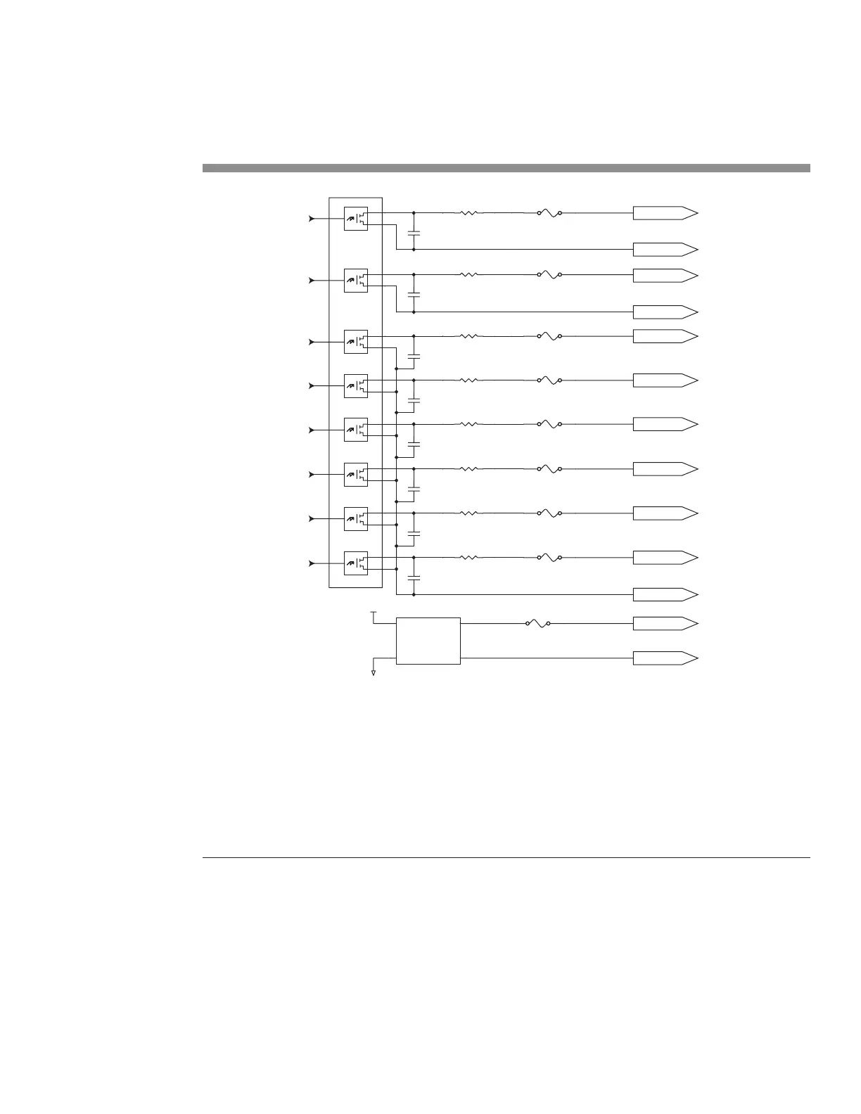
Input/Output circuitry
Figure 6-9 illustrates an equivalent circuit diagram of FH Flyer’s optically-isolated output circuitry.
Figure 6-9 FH Flyer’s equivalent output circuit