SYNRAD FH Series Flyer Operator’s Manual Version 3.4
160
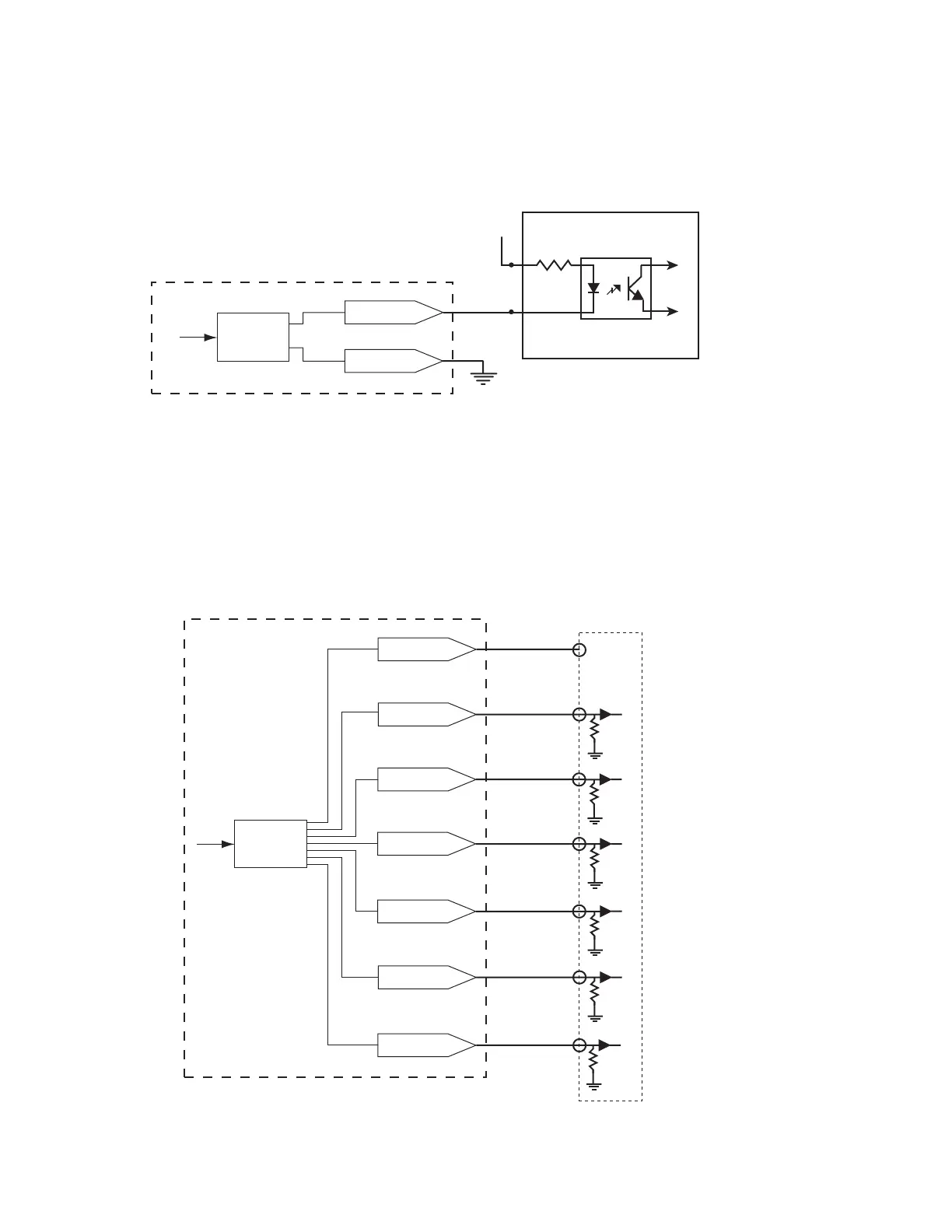
Sample output circuits
Flyer Output
Circuitry
OUT2–7_B
OUT7_A
V+
OUT6_A
OUT5_A
OUT4_A
OUT2_A
OUT3_A
+V
DC
FH Flyer Output Section
IN0_B
IN0_A
Flyer Output
Circuitry
FH Flyer’s optically-isolated outputs are used to create exible automated systems. Typically, one of these
outputs is used to indicate completion of a mark. Another might drive a warning light when the laser
beam is active, or increment a parts counter. Several circuits for interfacing to Flyer outputs are shown on
the following pages. FH Flyer outputs are designed for compatibility with standard industrial control circuit
voltages in the range from 5 V to 24 VDC. Because Flyer outputs OUT0–OUT7 are bipolar, the circuits
shown below can connect to either the “A” or “B” input connection. See Table 6-10 for a listing of pos-
sible output signal configurations.
To isolated I/O module
Figure 6-10 illustrates a simple output connection. In this configuration, the output is sinking