technical reference
SYNRAD FH Series Flyer Operator’s Manual Version 3.4
161
current. When sizing V
DC
remember to account for the voltage drop across Flyer’s 900-
ohm output resistance. See Table 6-10 for a listing of possible output signal
configurations.
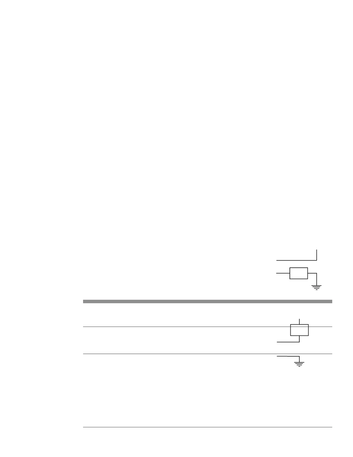
Input/Output circuitry
Figure 6-10 Flyer output to isolated I/O module
To PLC or logic interface
Figure 6-11 illustrates Flyer’s bipolar outputs connected to a PLC DC input module. When
the Flyer output is ON, it sources current and drives the PLC logic input to a logic high state.
See Table 6-10 for a listing of possible output signal configurations.
Figure 6-11 Flyer output to PLC input module
Input/Output circuitry
load is returned back to the I/O power supply’s return or common.
Table 6-10 Possible output signal configurations for FH Flyer
Output High Side Output Low Side
OUT0_A OUT0_B
OUT0_B OUT0_A
OUT1_A OUT1_B
OUT1_B OUT1_A
OUT2_A
1
OUT2–7_B
OUT3_A
1
OUT2–7_B
OUT4_A
1
OUT2–7_B
OUT5_A
1
OUT2–7_B
OUT6_A
1
OUT2–7_B
OUT7_A
1, 2
OUT2–7_B
Table 6-10 lists possible ways you can connect Flyer outputs to your automation control circuits. Outputs
OUT0 and OUT1 are bipolar outputs with isolated return lines. For example, if OUT0_A is wired to the
circuit’s high (+V) side, then wire OUT0_B to the low (return) side or you can connect OUT0_B to the
high side and connect OUT0_A to the low side.
Outputs OUT2 through OUT7 share a common return line, OUT2–OUT7_B. When wiring your external
circuit, the common return line, OUT2–OUT7_B is always connected to either the supply’s high (V+)
side or the supply’s low (return). The “A” side of the outputs, OUT×_A, are always tied to the load.
For example, refer back to Figure 5-11. The common return line, OUT2–OUT7_B, is tied to the PLC’
+
s
high (V+) side. OUT2_A through OUT7_A are tied to the high side of the load and the other side of the
LOAD
OUT2–7_B
through OUT7_A
LOAD
through OUT7_A
OUT2–7_B