INSTRUCTION MANUAL
52
Rotate the measuring device parts to set all
0-lines to the same side of the device.
There are two (2) alignment pieces inside the
device, that will t the collaring tool axis key
grooves.
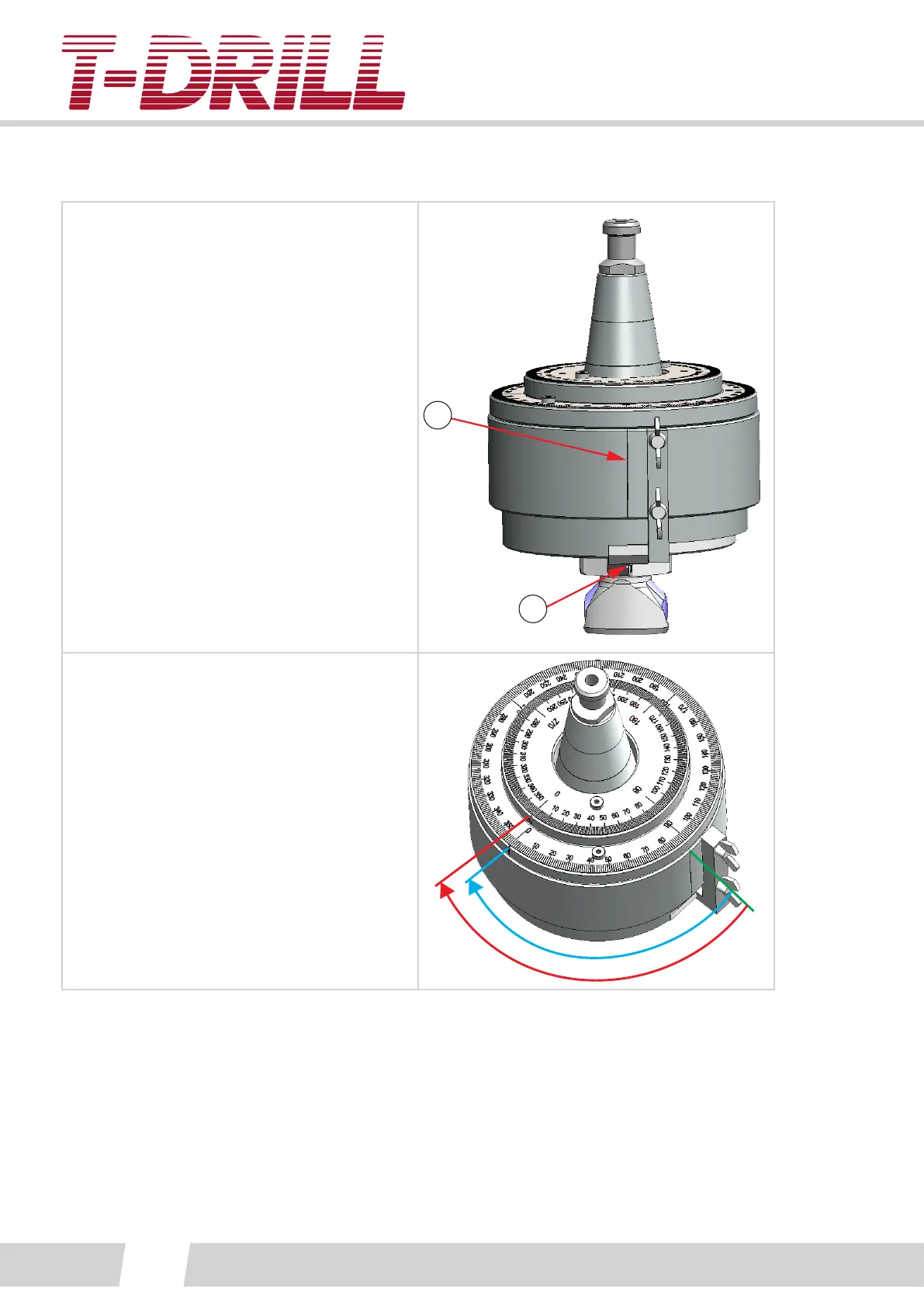
Loosen the posioning peg by the wing bolts.
Place the device on the collaring tool and
Rotate tool against the stopper, and ghten
to place wit posioning peg (Tightened peg
will prevent rotang). The zero line (1) of the
device is placed so that it is in the middle of
the drive key / trimming blade holder (2).
1
2
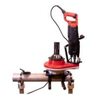
The angle dierence can be now calculated
from the dial values.
Values are read clockwise.
The outer dial shows the angle dierence
between the drive wheel and drill core
(S2), inner dial shows the angle dierence
between the tool holder cone and drill core
(S1).
Read the angle dierence from the dials:
S1 angle dierence xx°
S2 angle dierence yy°
S1
S2