INSTRUCTION MANUAL
66
The reference seng tool is xed to the main frame. Set the reference zero point to
which all distances are compared to.
Switch the machine to MANUAL from the control panel switch. Place the posioning peg
into the milling tool adapter. Place the milling tool adapter to the machine chuck.
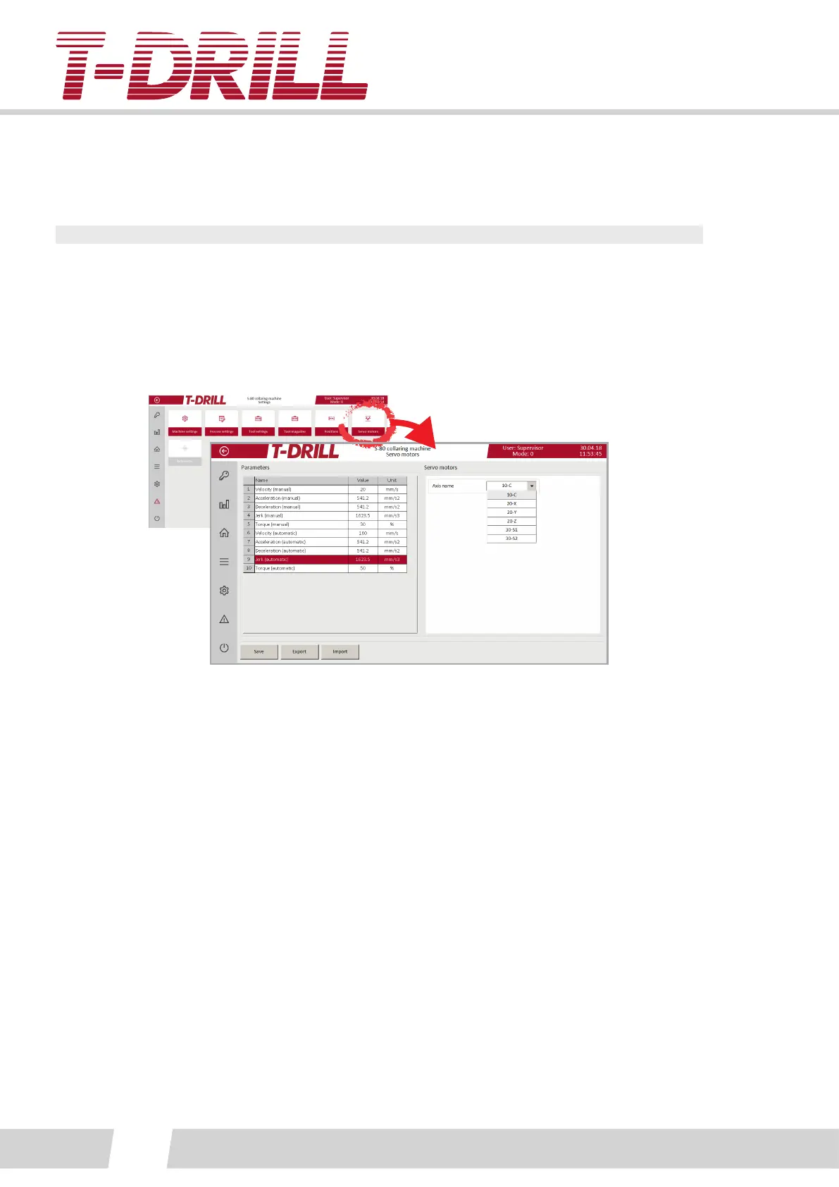
Set all torque and speed values to minimum to avoid collision and breakage from the
servo screen:
X- and Y-axis reference. Lower down the posioning peg very close to the surface of the
reference seng point tool using manual screen funcons.
Aach a small dial gauge (with magnec leg) to the spindle axle, and posion the peg to
the center of the reference seng tool:
See photo. Point the gauge p to ref. tool body. Rotate the spindle with hand, drive
sideways using manual screen funcons and slow speed. (The dial gauge allowed reading
dierence is 0.01mm).
Set the reference to the machine program from the “Reference” screen.
Posion the Z-axis using the same xed reference tool, remove tool holder and peg rst.
Set the torque (manual) to zero, and the spindle will drop down on its own. Let it go
down to the surface of the reference tool. Rotate the spindle counter surfaces against the
reference tool surfaces.
Set the reference to the machine program from the “Reference” screen.