INSTRUCTION MANUAL
74
¨NOT!¨
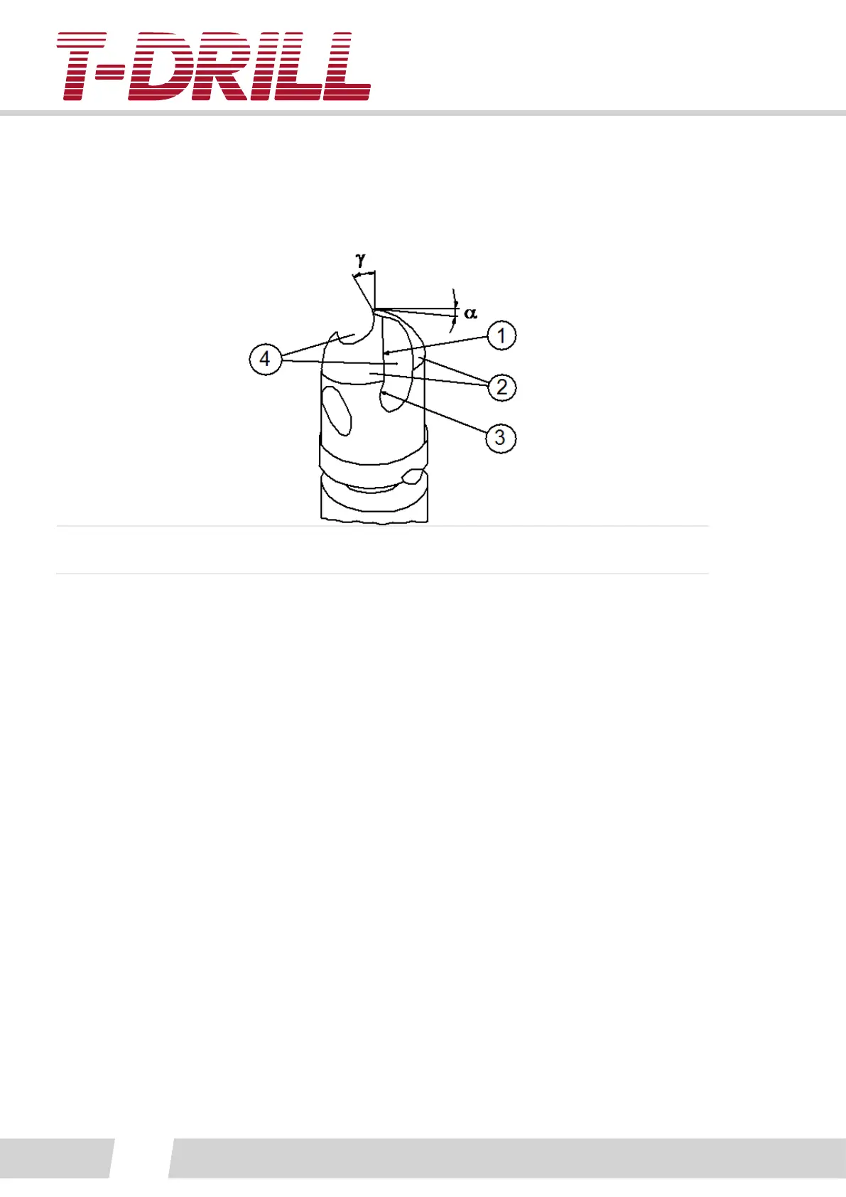
The parts of the bit: α = Clearance angle, ɣ = Chisel edge angle, 1. Cung edge, 2. Body
clearance surface (land), 3. Rake face, 4. Flute.
The patented cung geometry of the T-DRILL bit is designed in such a way that a perfect
pilot hole without burrs can be achieved at a low feed rate. However, this presupposes
that the cung edge is always kept sharp.
When the cung performance of the bit declines, it does not seem to penetrate the tube
surface easily or burrs occur on the edge of the pilot hole, it is me to resharpen. (Note!
Burrs may also be a sign of insucient lubricaon). Use of a dull bit must be avoided,
because a dull bit wears out very quickly and thus its life expectancy will be relavely
short.
The bit is resharpened at the rake face only. The body clearance surface is never to be
sharpened, because even the slightest variaon in the anding angle will radically reduce
the cung characteriscs of the bit.
For the resharpening the following equipment is needed:
- A tool grinding machine equipped with a vercally ltable rotary table
- A ne-grained, thin grinding wheel which ts in the ute
- A straight pin which ts in the cung-groove by means of which it is easier to set the bit
in the correct posion.
1. Fasten the drill shank in the clamping xture and put the straight pin into the ute. Set
the pin parallel with the slide bars of the grinding machine carriage both vercally and
horizontally. (See gure next).