Section II – Pre-Installation Considerations
MN06135 Issue/Rev. 1.3 (6/17) 3
Mechanical
In addition to the following, all previous warnings
and cautions should be reviewed before installation.
1. A solid base (pedestal or shelf) should be use
d
t
o support the explosion-proof AccuLoad III
housing.
Weight: = 50 lb. (22.7 kg) ALIII-S Hardware
Weight: = 125 lb. (57.5 kg) ALIII-Q Hardware
2. The location and the height of AccuLoad III
should be selected to permit easy viewing of th
e
di
splay and to provide convenient access to the
keypad by all users.
3. Access for servicing AccuLoad III is through the
front cover. For ease of service and removal of
parts the cover must swing open more than 90°
.
T
he explosion-proof AccuLoad III is hinged o
n
t
he left.
4. Conduit entry to the explosion-proof AccuLoa
d
III is both through the bottom and top. The top
entries are used for those units where the C
I-
VACON
Grounding and overfill board is installed.
For the ALIII-S hardware there are three 1-1/4"
11.5 NPT conduit entrances in the bottom of t
he
uni
t and two 1" 11.5 NPT conduit entrances in
the top of the unit. For the ALIII-Q hardware
there are two 1-1/4" 11.5 NPT conduit entrances
and five 1" 11.5 NPT conduit entrances in the
bottom of the unit and one 1" 11.5 NPT conduit
entrance in the top of the unit.
5. In warm climates, AccuLoad III should be shad-
ed from direct sunlight. The maximum external
temperature of the AccuLoad III housing must
not exceed 140°F (60°C) to ensure that the in-
ternal temperature limit is not exceeded.
Electrical
1. All DC wiring must be routed into AccuLoad III
through the conduit entries located in the bottom
of the housing. Do not route DC and AC wiring
through the same conduit entry.
2. T
he DC signal wires must be multi-conductor
shielded cable of 18 to 24 AWG minimum strand
copper.
Note: The following recommendations are based on our
knowledge of the electrical codes. The local electrical codes
should be reviewed to ensure that these recommendations follow
the local code. Also installation manuals of all the equipment be-
ing wired into the AccuLoad should be reviewed for transmission
distances and wire recommendations.
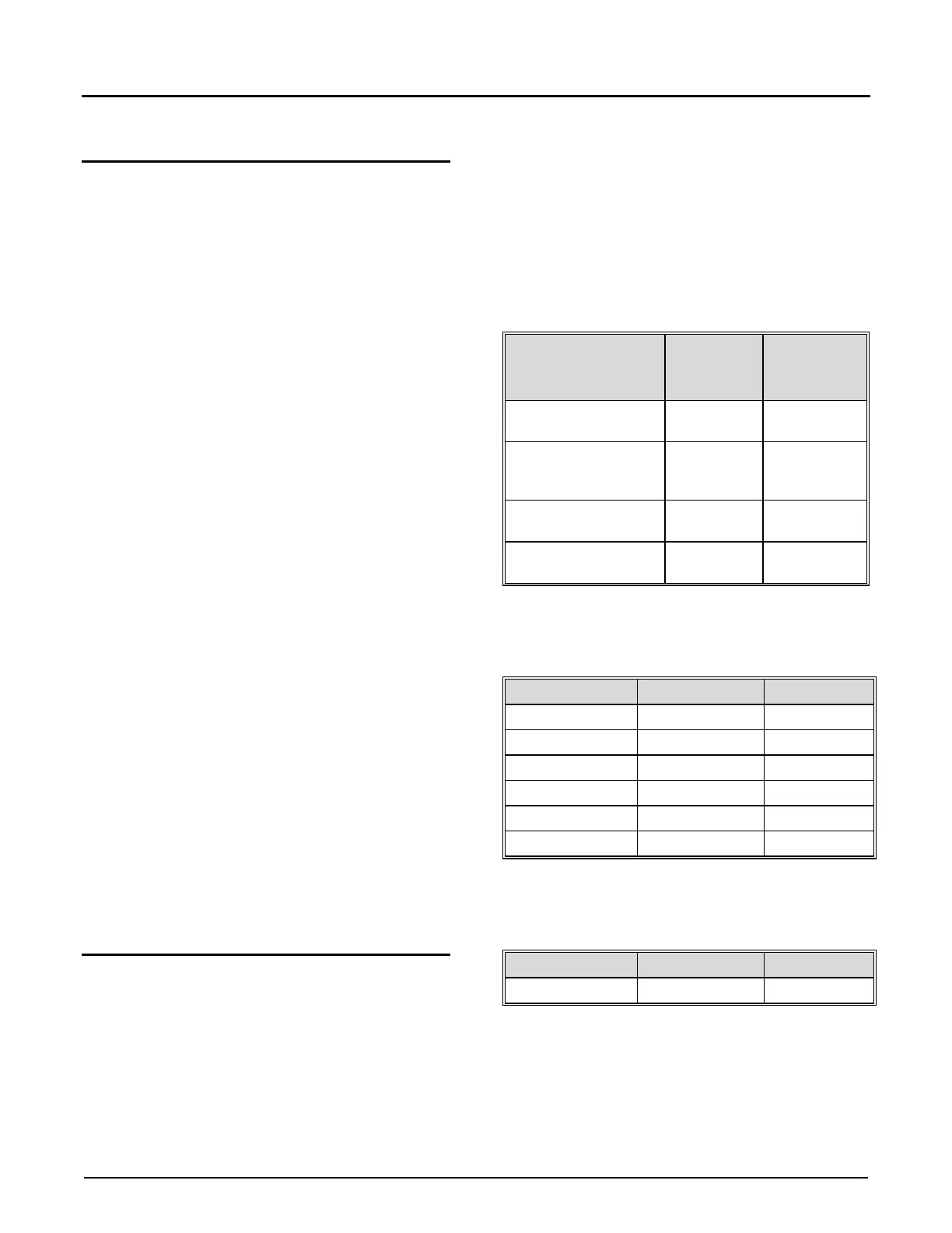
Table 1. Typical Wire Sizes
Equipment
Number &
Gauge of
Belden
Number or
Equivalent
Transmitters
4 / 18 Ga.
4 / 20 Ga.
9418
8404
Temp. Probes
Density & Pressure
Transmitters
4 / 22 Ga.
8729
OR
9940
EIA-232
Communications
3 / 24 Ga. 9533
EIA-485
Communications
4 / 24 Ga. 9842
T
able 2. Maximum Cable Length and Baud Rate
(EIA-232)
Baud Rate Feet Meters
38,400 250 75
19,200 500 150
9,600 1,000 305
4,800 2,000 610
2,400 4,000 1,220
1,200 4,000 1,220
T
able 3. Maximum Cable Length and Baud Rate
(EIA-485)
1,200 to 38,400 4,000 1,220
No
te: For Ethernet communications, refer to standard IT
practices for connecting any AccuLoad using routers,
hubs, switches, etc.