Section II – Pre-Installation Considerations
MN06135 Issue/Rev. 1.3 (6/17) 4
3. All AC wiring must be routed into AccuLoad III
through the conduit entries located in the bottom
of the housing. Connectors sized for a maximum
of 14-gauge wire, consult the local electrical
codes for the minimum AC wire size required for
your application. Do not route AC and DC wiring
through the same conduit entry.
4. All AC wiring should be stranded copper and
must comply with federal, state and local codes
and specifications.
5. Two separate AC circuits must be provided from
the breaker panel. One circuit will supply isolat-
ed power to the AccuLoad III electronics (in-
strument power). The second circuit will supply
power to the external devices.
6. For proper operation the AccuLoad III must
be
earth grounded. The grounding point should be
as close to the unit as possible. To ensure proper
earth ground:
a) The resistance between the ground lug in
the AccuLoad III and the grounding point
must not exceed 2 Ω.
b) The proper grounding point is a ½" to ¾" di-
ameter copper stake that extends into the
water table. Where this is not practical, a
ground plane may be used.
Note: Electrical conduit, piping, and structural steel are
not
considered proper grounding points for equipment
using electronics.
c) No other devices, except AccuLoad IIIs and
ancillary equipment such as load printers,
should be connected to any point in the
grounding circuit.
7. If external relay permissives are used in series
with AccuLoad III relays, an RC network must
be
pl
aced in parallel with the permissive to prevent
a false turn-on of the AccuLoad III relays. Rec-
ommended RC network = 0.1 UF capacitor and
a 680 Ω resistor (Electrocube part number RG
2031-11).
8. Interposing relays must be installed between th
e
pum
p controller, alarming device, and the Accu-
Load III permissive sense relays.
Environmental
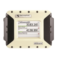
Models ALIII-S-XP and ALIII-Q-XP
The enclosures of Explosion / Flame proof models
are manufactured from aluminum alloy, and are de-
signed to be operated in normal environmental con-
ditions free of corrosive agents.
In areas including but not limited to environmentally
corrosive atmospheres, special considerations for
additional environmental protections shall be made if
installing into near shore areas that are subject to
wind borne salt sea water spray and subject to pos-
sible continuous accumulations of wetted salt water
on the equipment. The recommended protection is
exclusion of the environment by placing the equip-
ment into secondary protected environment such as
a kiosk or a control room. If exclusion of the envi-
ronment is not possible, then extra means must be
taken to maintain the equipment integrity, this in-
cludes frequent cleaning and inspection intervals.
See Section IV for additional information.
In areas where the ambient temperature is very
high, it is recommended that the equipment be in-
stalled under a canopy / sun shield to limit direct
sunlight radiation.
In areas of high humidity (tropical) or with varying
temperature swings, it is recommended to place
TechnipFMC P/N 647 001 443 or similar desiccant
packs inside of the enclosures, and to maintain
these while in service.
 Loading...
