Section IV – Diagrams
MN06135 Issue/Rev. 1.3 (6/17) 34
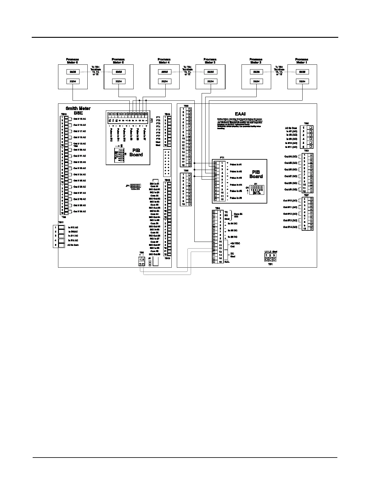
Figure 21. Wiring Diagram, Promass 80, 83, and 84 Single Pulse
Note: Wiring between transmitter and Accuload should be done with a shielded cable per each transmitter. If selected cable utilizes twisted
pairs, do not run more than one signal in a twisted pair.
Caution: For clarity, shields not shown. Connect shields to terminals 3, 13, 14, or 15 of Terminal Block 4.
Promass Wire Codes:
Terminal 22/24: +
Terminal 23/25: -
Note: The pulse input circuitry on the PIB has 1.6kΩ of current limiting resistance “built-in” so that an external pull-up resistor is not required
when an open collector output device is connected as shown.