R2A R2B R2C R2D R2N
R1A
R1B
R1C
R1D
R1N
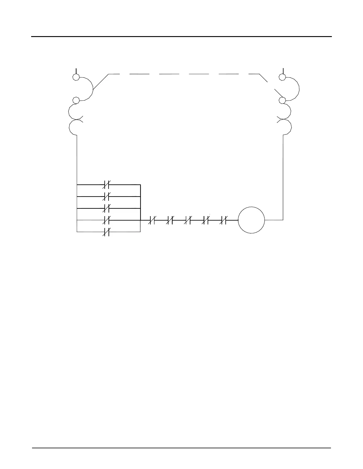
Notes:
1.
T
his figure shows wiring for a typical pump and alarm contact array for multipl
e
A
ccuLoad III-controlled load arms if the pump and alarm control options are used.
2.
R1
A through R1N represent the contacts of the customer-supplied relay (R1)
on
th
e output of the AccuLoad III pump permissive contacts.
3.
R2
A through R2N represent the contacts of the customer-supplied relay (R2)
on
the
output of the AccuLoad III alarm permissive contacts.
4. An interposing relay must be used between the pump controller and the Acc
uLoad
III p
ump contacts.
Pump Controller
L1
N
B1B1